
User's Manual

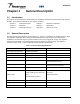
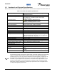
Table Of Contents

044-05117
1-3 Functional and Physical Specifications
Electrical, mechanical, and environmental specifications for the G3L-850-135 amplifier are listed in Table 1-2.
Table 1-2. G3L-850-135 Amplifier Specifications
Frequency Range 869-894 MHz; 25 MHz bandwidth (lowest to highest
transmitted frequency)
Minimum Channel Spacing 1 to 8 GSM carriers
Total Maximum Input Power -12.21 dBm @ 135 Watts (to achieve rated power);
-11.91 dBm max. -6.0 dBm or greater causes input
overdrive shutdown.
Total Output Power 135 Watts (7GSM and 1EDGE) @27Vdc
120 Watts (GSM/EDGE) @26Vdc to 30Vdc
110 Watts (W-CDMA) @26Vdc to 30Vdc
Intermodulation Distortion
and In-Band Spurious:
-65 dBc (Min) @ +26 to +28 Vdc @ 135 Watts; 600 KHz
channel spacing within 25 MHz bandwidth*
RF Gain at 869 to 894 MHz
63 dB ±1 dB
Gain Flatness:
±0.5 dB @ 27 Vdc ±1 Vdc
Gain Variation Over Temperature:
±0.5 dB from 26 Vdc to 28 Vdc over -20° to +50° C
Output Protection: Mismatch protected
Input Port Return Loss: Equal to or greater than 14dB
Out of Band Spurious: Better than -60 dBc, +26 Vdc to +28 Vdc
Duty Cycle: Continuous
DC Input Power:
+27 Vdc ± 1 Vdc, 34.1 Amps typical, 36 Amps max @ 135
Watts; operational range +21.0 Vdc to 30 Vdc amplifier will
disable at < 20.5 Vdc or > +30.5 Vdc.
Operating Temperature: -33 ºC. to +50 ºC.
Storage Temperature: -40 ºC. to +85 ºC.
Operating Humidity: 5 % to 95 % relative humidity (non-condensing)
Storage Humidity: 5 % to 95 % relative humidity (non-condensing)
RF Input / Output / Status / Alarm /
Control / DC Input Connectors:
21-Pin D-Subminiature combo connector
Maintenance Port
RJ-11, RS-232 signaling (for factory use only)
Switches
Reset/On/Off Switch
Indicators:
STATUS
LED; Green (normal), Yellow (minor alarm), Red (critical
alarm)
Dimensions: 35.46 cm wide, 9.56 cm high, 45.0 cm deep (including
handles)
Weight: 12.97 kg
Note
This Powerwave product is designed to operate within the normal operating (typical operating)
ranges or conditions specified in this document. Operation of this equipment beyond the
specified ranges may cause (1) spurious emissions that violate regulatory requirements; (2)
the equipment to be automatically removed from service when maximum thresholds are
exceeded; or (3) the equipment to not perform in accordance with its specifications. It is the
operator's responsibility to ensure this equipment is properly installed and operated within
Powerwave operating specifications to obtain proper performance from the equipment and
to comply with regulatory requirements.
1-2 Installation and Service Manual - G3L-850-135 Multi-Carrier Power Amplifier