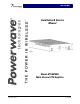
930-1990 MHz Installation & Service Manual Model NTUM30DA Multi-Channel PCS Amplifier Copyright Powerwave Technologies, Inc., June 2003. All rights reserved 044-05141 Rev.
NTUM30DA Installation & Service Manual © 2003 Powerwave Technologies Incorporated. All rights reserved. Powerwave Technologies, and the Powerwave logo are registered trademarks Powerwave Technologies, Inc. reserves the right to make changes to the documentation and equipment, including but not limited to component substitution and circuitry changes. Changes that impact this manual may subsequently be incorporated in a later revision of this manual. June 2003 Powerwave Technologies, Inc. 1801 East St.
NTUM30DA Installation & Service Manual Table Of Contents Section 1 General Description Par. No. 1-1 1-2 1-3 Page No. Introduction ..................................................................................................................................................... 1-1 General Description....................................................................................................................................... 1-1 Functional and Physical Specifications ..........................
NTUM30DA Installation & Service Manual Section 4 Principles of Operation (continued) Par. No. 4-7.2.1 4-7.2.2 4-7.2.3 Page No. Over Temperature Shutdown Alarm ........................................................................................................... 4-5 Power Supply Shutdown Alarm .................................................................................................................. 4-5 High DC Power Consumption Shutdown Alarm ..................................................
NTUM30DA Installation & Service Manual Section 1 General Description 1-1 Introduction This manual contains information and procedures for installation, operation, and maintenance of Powerwave’s model NTUM30DA multichannel power amplifier (MCPA). The manual is organized into six sections as follows: Section 1. General Description Section 2. Installation Section 3. Operating Instructions Section 4. Principles of Operation Section 5. Maintenance Section 6.
NTUM30DA Installation & Service Manual Table 1-1 NTUM30DA Multichannel Power Amplifier Functional Specifications Frequency Range 1930-1990 MHz (60 MHz Bandwidth) *Instantaneous Bandwidth 20 MHz Input Power 1.4 dBm without damage (operating); 15 dBm without damage (non-operating) Continuous Average Output Power 45 Watts (46.53 dBm) Mode 1 30 Watts (44.77 dBm) Mode 2 Frequency Offset Spurious Emissions @ Maximum Rated Output Power Fcl: lower frequency center of the emission block.
NTUM30DA Installation & Service Manual Table 1-1 (Cont.
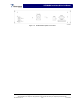
NTUM30DA Installation & Service Manual Figure 1-4. NTUM30DA Amplifier Front Panel Copyright Powerwave Technologies, Inc., June 2003. All rights reserved All specifications are subject to change without notice. Contact the factory for complete performance data. 1-4 June 2003 044-05141 Rev.
NTUM30DA Installation & Service Manual Section 2 Installation 2-1 Introduction This section contains unpacking, inspection, and installation instructions and recommendations for the Model NTUM30DA Multi Channel Power Amplifier. Carefully read all material in this section prior to equipment unpacking or installation. Also read and review the operating procedures in section 3 prior to installing the equipment. It is important that the licensee perform these tasks correctly and in good faith.
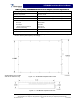
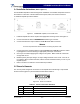
NTUM30DA Installation & Service Manual 2-4 Installation Instructions (Refer to figure 1-1) The NTUM30DA amplifier module is designed for installation on a heatsink that permits access to the module for connection of the RF cables and the power, alarm, and control connectors. To install the amplifier proceed as follows: Figure 2-1 NTUM30DA Amplifier, Front Panel View 1. Install the amplifier and secure in place with appropriate mounting screws. See figure 2-1. 2.
NTUM30DA Installation & Service Manual 2-6 Data I/O Connector The alarms and sensing connections on the amplifier are made through a 14-pin micro-fit connector (figure 2-3) and are listed and described in table 2-2.
NTUM30DA Installation & Service Manual Section 3 Operating Instructions 3-1 Introduction This section contains operating instructions for the Multicarrier Cellular Amplifier. 3-2 Initial Start-Up & Operating Procedures There are no operating controls or indicators on the NTUM30DA amplifier module. To perform the initial start-up, proceed as follows: 1. Verify that all input and output cables are properly connected, per section 2.
NTUM30DA Installation & Service Manual Section 4 Principles of Operation 4-1 Introduction This section contains a functional description of the multichannel power amplifier (MCPA). 4-2 RF Input Signal The maximum input power should not exceed the limits specified in table 1-1. 4-3 RF Output Load The load impedance should be as good as possible (1.5:1 or better) in the working band for good power transfer to the load.
NTUM30DA Installation & Service Manual 4-4.3 Driver Amplifier The driver amplifier consists of two stages of class AB amplification, which provide the approximately 40% of the gain in the 60 MHz frequency band from 1930 MHz to 1990 MHz. 4-4.4 Main Amplifier The main amplifier employs two class AB amplification stages for maximum efficiency. It provides approximately 40% of the gain in the 60 MHz frequency band.
NTUM30DA Installation & Service Manual 4-6 Power Distribution Primary DC power for the amplifier is provided by the host system. The amplifier generates all the required voltages internally from the main source. 4-7 Amplifier Alarms 4-7.1 Minor Alarms When a minor alarm condition occurs, the alarm is latched into a minor alarm condition. The amplifier alarm state is read by the BTS the next time the amplifier is poled by the BTS.
NTUM30DA Installation & Service Manual 4-7.1.2 Error Loop Cancellation Alarm (2nd Loop Alarm) During normal operation, if the 2nd Loop is not locked for 30 seconds a Error Loop Cancellation Alarm is declared. During power-up, the BTS waits for 30 seconds to allow the 2nd Loop to lock. When the error amplifier is first turned on, the Error Loop Cancellation Alarm ON status is on until the loops converge.
NTUM30DA Installation & Service Manual 4-7.2 Major Alarms When a major alarm condition occurs, the alarm is latched into a major alarm condition. The amplifier alarm state is read by the BTS the next time the amplifier is poled by the BTS. After the alarm status is sent the major alarm register is not cleared. If the amplifier receives a “Enable Command” or “Clear Alarms Command”, all major alarms will be cleared. If the amplifier is disabled, all major alarms are also cleared.
NTUM30DA Installation & Service Manual 4-7.2.3 High DC Power Consumption Shutdown Alarm If input power exceeds 417W in Mode 1 or 330W in Mode 2, for one second, the High DC Power Consumption Shutdown Alarm is set.
NTUM30DA Installation & Service Manual Section 5 Maintenance 5-1 Introduction This section contains periodic maintenance and performance test procedures for the multichannel power amplifier. It also contains a list of test equipment required to perform the identified tasks. NOTE Check your sales order and equipment warranty before attempting to service or repair the unit. Do not break the seals on equipment under warranty or the warranty will be null and void.
NTUM30DA Installation & Service Manual Section 6 Troubleshooting 6-1 Introduction This section contains a list of problems and a few suggested actions that may correct the problem. If the suggested corrective action does not eliminate the problem, please contact your Powerwave field representative or the factory for further instructions. NOTE Check your sales order and equipment warranty before attempting to service or repair the unit.
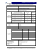
NTUM30DA Installation & Service Manual Field Failure Report RMA No.: __________ S/N: __________ Region: ________________ Customer: ___________________ Technician: ___________________ Manufacture Date: ___________ Failure Date: ___________ Phone No.