
User Manual
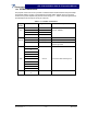
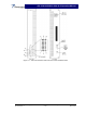
Table Of Contents

G3L-2100-30-B/G3L-2100-30-C Operation Manual
Section 1 General Description
1-1 Introduction
This manual contains information and procedures for the operation of the model G3L-2100-30-B
and G3L-2100-30-C Wideband (WCDMA) Multi-Carrier Power Amplifier (MCPA). The manual is
organized into the following sections and appendix.
Section 1 General Descri
p
tion
Section 2 O
p
eration
App
endix
A
S
p
ecifications
1-2 General Description
The amplifiers are wideband, linear, feed-forward power amplifiers (WPAs) that operate in the 60
MHz frequency bandwidth from 2110 to 2170 MHz with an instantaneous bandwidth of 20 MHz.
The amplifier provides linear amplification for single or multi-carrier WCDMA signals. The amplifi-
ers communicate with the base station via a TLCI control interface bus; passing alarm and meas-
urement information to the base station and receiving control information from the base station.
1-3 Hardware Interface
There are three groups of interface connections located on the amplifier chassis. These are RF,
power, and control interface (TLCI bus) as described in the paragraphs that follow.
1-3.1 RF
The RF interface is located on the power amplifier front panel consists of the RF-In (TX-In) and
RF-Out (TX-Out) connectors as shown in Figure 1-1.
1-3.2 Power Supply
Power supply voltages (-48 VDC or 230 VAC) from the base station subrack are connected to the
amplifier via connector X3, pins A – D located on the power amplifier rear panel as shown in fig-
ure 1-1. Table 1-1 lists the voltages and descriptions for each pin.
Table 1-1 Primary Power Connections
Signal Group X3 Connector
Pin
Signal Name Description
D -48VDC DC Minus (isolated from amplifier
chassis)
DC
E +48VDC DC Plus (isolated from amplifier chas-
sis)
A L AC Phase (isolated from amplifier
chassis)
B N AC Zero (isolated from amplifier chas-
sis)
AC
C PE AC Protective Ground (connected to
chassis)
Copyright Powerwave Technologies, Inc., March 2003. All rights reserved
044-05133 Rev. A 1-1 March 2003