
User Manual


MCA9129-90MCA9129-90-A Installation & Service Manual
Ó Copyright Powerwave Technologies, Inc., July 2001. All rights reserved
044-05060 Rev. C 5-2 July 2001November 2002
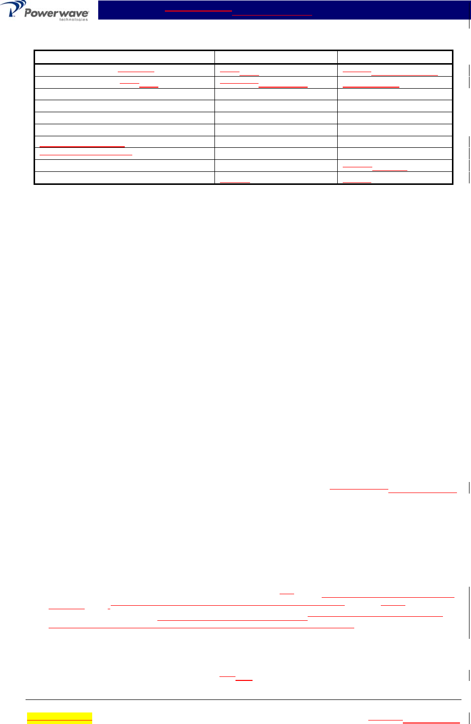
Table 5-2 Test Equipment Required
Nomenclature Manufacturer Model
Signal Generator (4 each) H.P.RDL 8656BIMD-801D-03A
20 dB Attenuator, 250 500 Watt Tenuline Weinschel WA53-20-34
20 dB Attenuator, 20 Watt (2 each) Tenuline
Spectrum Analyzer H.P. 8560E
Coax Directional Coupler H.P. 778D
Power Meter / Sensor H.P. 437B / 8481A
Variable Attenuator
Four Tone Combiner
Network Analyzer H.P. 8753C8753ES
Current Probe Agilent 1146A
5-4 Cleaning Air Inlets/Outlets
The air inlets and outlets should be cleaned every 30 days. If the equipment is operated in a se-
vere dust environment, they should be cleaned more often as necessary. Turn off DC power
source before cleaning fans. If dust and dirt are allowed to accumulate, the cooling efficiency may
be diminished. Using either compressed air or a brush with soft bristles, loosen and remove ac-
cumulated dust and dirt from the air inlet panels.
5-5 Performance Test
Performance testing should be conducted every 12 months to ensure that the amplifier system
meets the operational specifications listed in table 5-3. Also verify system performance after any
amplifier module is replaced in the field. The test equipment required to perform the testing is
listed in table 5-2, and the test setup is shown in figure 5-1.
NOTE
The frequencies used in this test are typical for an amplifier with a 25-MHz band from
869 MHz to 894 MHz. Select evenly spaced F1, F2, F3, and F4 frequencies, that
cover the instantaneous bandwidth of your system.
5-5.1 Amplifier Performance Test
This test is applicable to a subrack equipped with one to four plug-in MCA9129-90MCA9129-90-A
amplifier modules. Perform the tests applicable to your system. To perform the test, proceed as
follows:
1. Connect test equipment to the subrack as shown in figure 5-1.
NOTE
Do not apply any RF signals at this time.
2. Turn on all four signal generators and set frequency F1
to 880, 881, 882, 883, 884, 885, 886
and 887 MHz., F2 to 881 MHz, F3 to 882 MHz, and F4 to 883 MHz. Adjust each signal gen-
erator output so that the composite power equals –12dBm.sum power output from all four
signal generators equals -4 dBm at the output of the 4-way combiner.
5-5.1.1 Single Amplifier IMD Test
3. Adjust attenuator for an input signal at –l2 -12dBm. Reset channel 1 amplifier with the front
panel ON/OFF/RESET switch, and set switch to ON. Set amplifiers 2, 3, and 4 to OFF. Ad-