
User Manual


MCA9129-90-A Installation & Service Manual
Ó Copyright Powerwave Technologies, Inc., July 2001. All rights reserved
044-05060 Rev. C 4-4 July 2001November 2002
Pre
A
mp
Pre
Main
Main
A
mp
Error
A
mp
Delay
Feed Forward Loop control
2nd Loop
Phase & Gain
1st Loop
Phase & Gain
Delay
A
larms & Display
+15 +5 -5
Power Supply
-40dB
-8.5dB
-40dB
RF Out
RFL
PWR
FWD
PWR
Front Panel
Smart Rack
+27VDC
Pre
Amp
Pre
Main
Main
Amp
Error
Amp
Delay
Feed Forward Loop control
2nd Loop
Phase & Gain
1st Loop
Phase & Gain
Delay
Alarms & Display
+15 +5 -5
Power Supply
-30dB
-10dB
-40dB
RF Out
RFL
PWR
FWD
PWR
Front Panel
Smart Rack
+27VDC
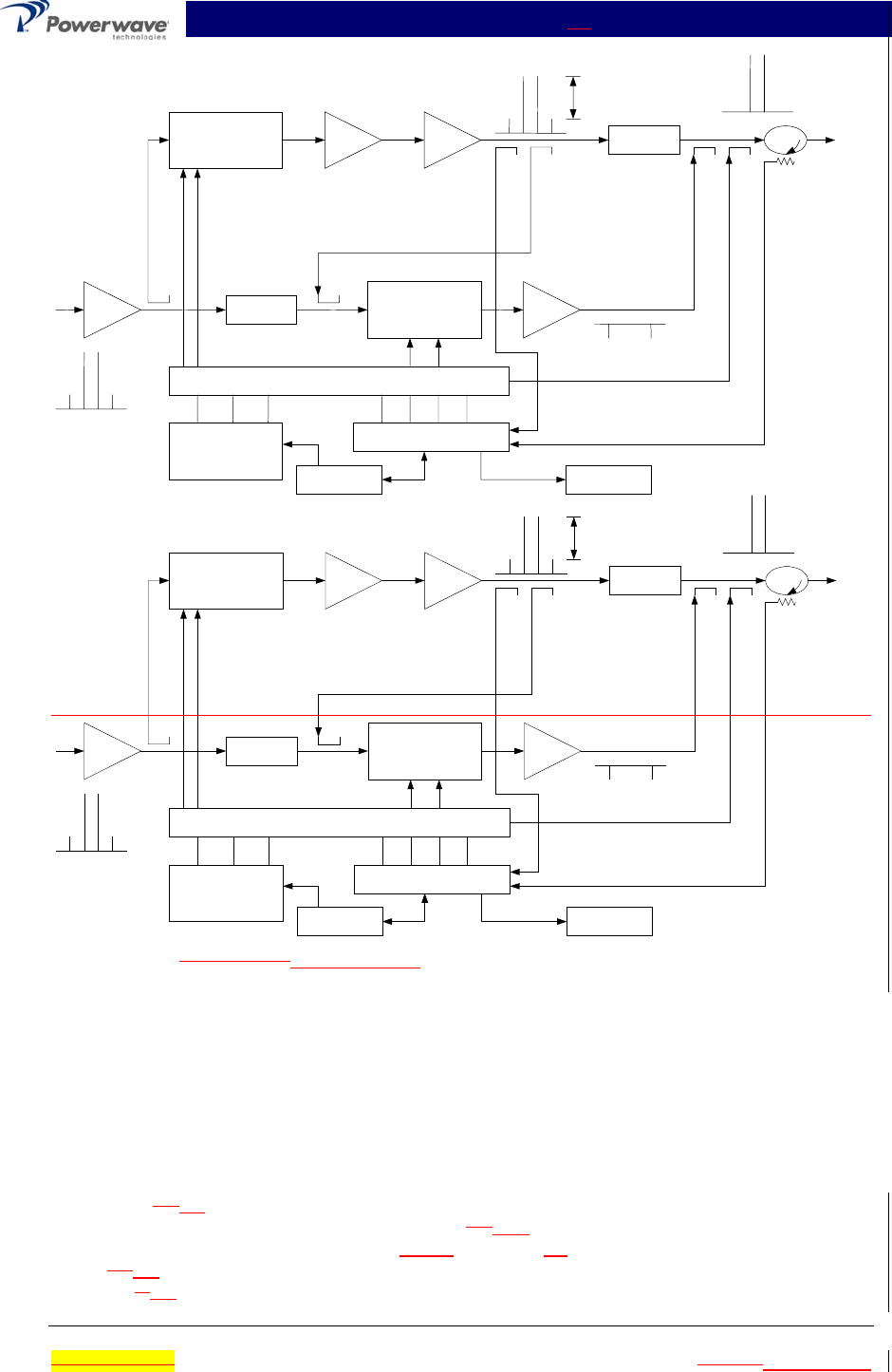
Figure 4-2 MCA9129-90MCA9129-90-A Power Amplifier Module Functional Block Diagram
The 2nd loop control section obtains a sample of the distortion added to the output signals by the
main amplifiers, phase shifts the signals by 180 degrees, then feeds it to the error amplifier.
There it is amplified to the same power level as the input sample and coupled on to the main out-
put signal. The final output is monitored by the 2nd loop and adjusted to ensure that the signal
distortion and IMD on the final output is canceled out.
4-5.1 Main Amplifier
The input and output of the amplifier employ three-stage, class AB amplifiers which provide ap-
proximately 30
15 dB of gain in the 25 MHz frequency band from 869 MHz to 894 MHz. The am-
plifier operates on +27 Vdc, and a bias voltage of +5 +12 Vdc, and is mounted directly on a heat
sink which is temperature monitored by a digital thermostat IC. If the heat sink temperature ex-
ceeds 92 85 °C, the thermostat opens and a high temperature fault occurs. The alarm logic con-
trols the +5 12 Vdc bias voltage that shuts down the amplifier.