
User Manual
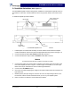
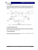
Table Of Contents

NTGS86AB Installation & Service Manual
Section 5 Maintenance
5-1 Introduction
This section contains periodic maintenance and performance test procedures for NTGS86AB
Single-Carrier Cellular Power Amplifier module.
NOTE
Check your sales order and equipment warranty before attempting to service or re-
pair the unit. Do not break the seals on equipment under warranty or the warranty will
be null and void. Do not return equipment for warranty or repair service until proper
shipping instructions are received from the factory.
5-2 Periodic Maintenance
Periodic maintenance requirements are listed in table 5-1. Table 5-1 also lists the intervals at
which the tasks should be performed.
Table 5-1 Periodic Maintenance
Task Interval Action
Inspection:
Cables and Connectors 12 Months Inspect signal and power cables for frayed insula-
tion. Check RF connectors to ensure they are tight.
Performance Tests No periodic maintenance is necessary beyond that
recommended by the base station manufacturer.
5-3 Amplifier Module Field Replacement
The NTGS86AB power amplifier module can be replaced in the field on site by a qualified techni-
cian with adequate ESD protection and experience maintaining RF power amplifiers and similar
equipment.
To replace a power amplifier module, proceed as follows:
1. Turn off the +26 Vdc power source to that specific amplifier module.
2. Disconnect the RF INPUT, RF OUTPUT, RF SAMPLE, and 18-pin Molex connectors.
3. Remove seven (7) screws that secure the amplifier module to the heat sink.
4. Carefully remove the amplifier module from the heat sink.
5. Remove any remaining Thermstrate from the heat sink. Use alcohol or other recommended
cleaning agent to achieve a clean heat sink mounting surface.
NOTE
Failure to completely remove old thermal grease, or the introduction of too much ther-
mal grease will dramatically alter the thermal transfer process between the amplifier
module and the heatsink.
6. Add Thermstrate thermal interface pad to surface of replacement amplifier, that mates with
heatsink. Use just enough Thermstrate to be evenly visible on the mounting surface.
7. Install replacement in reverse order of steps 1 through 4 above.
Copyright Powerwave Technologies, Inc., October 2002. All rights reserved
044-05126 Rev. A 5-1 October 2002