
User Manual

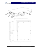
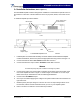
Table Of Contents

NTGS86AB Installation & Service Manual
2-5 Molex 18-Pin Power, Alarms, and Controls Connector
The power, alarms, and controls connections for the amplifier are made through the 18-pin Molex
connector shown in figure 2-2. The signals for each connector pin are listed and described in ta-
ble 2-1.
View looking into front of amplifier
Pin 18
Pin 10
Pin 9
Pin 1
Figure 2-2 Molex 18-Pin Power, Alarms, and Controls Connector
Table 2-1 Molex 18-Pin Power, Alarms, and Controls Connector Signal Descriptions
Pin Signal Description
1 TEMP_OUT 0-4.7 V temperature output
2 REV_PWR 0-4.7 V Reverse power detection
3 FWR_PWR 0-4.7 V forward power detection
4 GND GND
5 N/C N/C
6 ANX(-) - Anxiety output (RS-422 level)
7 GND GND
8 GND GND
9 GND GND
10 ANX(+) + Anxiety output (RS-422 level)
11 ENABLE(+) + Enable input (RS-422 level)
12 ENABLE(-) - Enable input (RS-422 level)
13 ALARM(+) + Alarm output (RS-422 level)
14 ALARM(-) - Alarm output (RS-422 level)
15 VDD +26 VDC
16 VDD +26 VDC
17 VDD +26 VDC
18 VDD +26 VDC
Copyright Powerwave Technologies, Inc., October 2002. All rights reserved
044-05126 Rev. A 2-3 October 2002