869-894 MHz Installation & Service Manual Model NTGS86AB Single-Channel Power Amplifier Copyright Powerwave Technologies, Inc., October 2002. All rights reserved 044-05126 Rev.
NTGS86AB Installation & Service Manual © 2002 Powerwave Technologies Incorporated. All rights reserved. Powerwave Technologies, and the Powerwave logo are registered trademarks Powerwave Technologies, Inc. reserves the right to make changes to the documentation and equipment, including but not limited to component substitution and circuitry changes. Changes that impact this manual may subsequently be incorporated in a later revision of this manual. October 2002 Powerwave Technologies, Inc. 1801 East St.
NTGS86AB Installation & Service Manual Table Of Contents Paragraph No. 1-1 1-2 1-3 1-4 Section 1 General Description Page No. Introduction ..................................................................................................................................................... 1-1 General Description....................................................................................................................................... 1-1 Functional and Physical Specifications .................
NTGS86AB Installation & Service Manual 6-3.2 Repackaging for Shipment ........................................................................................................................... 6-1 List Of Illustrations Figure No. 1-1 1-2 2-1 2-2 4-1 Page No. NTGS86AB Amplifier Isometric View......................................................................................................... 1-3 NTGS86AB Amplifier Top and Side Views ....................................................................
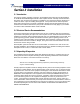
NTGS86AB Installation & Service Manual Section 1 General Description 1-1 Introduction This manual contains information and procedures for installation, operation, and maintenance of Powerwave’s model NTGS86AB Single-Channel Power Amplifier (SCPA) module. The manual is organized into six sections as follows: Section 1. General Description Section 2. Installation Section 3. Operating Instructions Section 4. Principles of Operation Section 5. Maintenance Section 6.
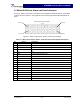
NTGS86AB Installation & Service Manual Table 1-1 NTGS86AB Single Channel Power Amplifier Functional Specifications Frequency Range 869 - 894 MHz (25 MHz Bandwidth) Maximum Average Input Power 13 dBm without damage; 0 dBm typical @ rated Pout Continuous Average Output Power 25 Watts (44 dBm) Spurious Emissions @ Maximum Rated Output Power (25 W/44 dBm) Frequency Offset Requirement Meas. Bandwidth 750 kHz -46 dBc 30 kHz 1.5 MHz -14dBm 37.5 kHz 1.
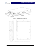
NTGS86AB Installation & Service Manual Test (RS485) RF Output RF Input RF Sample Power, Alarm and Control Interface Figure 1-1. NTGS86AB Amplifier Isometric View Figure 1-2. NTGS86AB Amplifier Top and Side Views with Dimensions Copyright Powerwave Technologies, Inc., October 2002. All rights reserved 044-05126 Rev.
NTGS86AB Installation & Service Manual Section 2 Installation 2-1 Introduction This section contains unpacking, inspection, and installation instructions and recommendations for the Model NTGA86AB Single-Channel Power Amplifier module. Carefully read all material in this section prior to equipment unpacking or installation. Also read and review the operating procedures in section 3 prior to installing the equipment. It is important that the licensee perform these tasks correctly and in good faith.
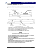
NTGS86AB Installation & Service Manual 2-4 Installation Instructions (Refer to figure 1-1) The NTGS86AB amplifier module is designed for installation on a heatsink that permits access to the module for connection of the RF cables and to the 18-pin power, alarms, and control connector. To install the amplifier proceed as follows: Power, alarms, and control interface RF interface Front True RMS coupler output Side Test connector Figure 2-1 NTGS86AB Amplifier Front and Side Connectors 1.
NTGS86AB Installation & Service Manual 2-5 Molex 18-Pin Power, Alarms, and Controls Connector The power, alarms, and controls connections for the amplifier are made through the 18-pin Molex connector shown in figure 2-2. The signals for each connector pin are listed and described in table 2-1.
NTGS86ABInstallation & Service Manual Section 3 Operating Instructions 3-1 Introduction This section contains operating instructions for the NTGS86AB Single-Carrier Cellular Power Amplifier module. 3-2 Initial Start-Up & Operating Procedures There are no operating controls or indicators on the NTGS86AB amplifier module. To perform the initial start-up, proceed as follows: 1. Verify that all input and output cables are properly connected per section 2.
NTGS86AB Installation & Service Manual Section 4 Principles of Operation 4-1 Introduction This section contains a functional description of the NTGS86AB Single-Carrier Cellular Power Amplifier module. 4-2 RF Input Signal The maximum input power should not exceed the limits specified in table 1-1. 4-3 RF Output Load The load impedance should be as good as possible (1.5:1 or better) in the working band for good power transfer to the load.
NTGS86AB Installation & Service Manual 4-4.3 Main Amplifier The main amplifier is a class AB amplification stage for maximum efficiency. The RF output signal from the main amplifier is then applied to an isolator. The amplifier power performance is monitored by the microprocessor via the forward and reverse detectors. The final output power is typically 44 dBm. The amplifier operates on +26 Vdc with gate bias voltages controlled by the microprocessor.
NTGS86AB Installation & Service Manual Section 5 Maintenance 5-1 Introduction This section contains periodic maintenance and performance test procedures for NTGS86AB Single-Carrier Cellular Power Amplifier module. NOTE Check your sales order and equipment warranty before attempting to service or repair the unit. Do not break the seals on equipment under warranty or the warranty will be null and void.
NTGS86AB Installation & Service Manual Section 6 Troubleshooting 6-1 Introduction This section contains a list of problems and a few suggested actions that may correct the problem. If the suggested corrective action does not eliminate the problem, please contact your Powerwave field representative or the factory for further instructions. NOTE Check your sales order and equipment warranty before attempting to service or repair the unit.