
User's Manual
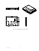
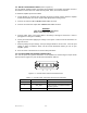
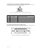
Table Of Contents

044-xxxxx Rev. x
ii
TABLE OF CONTENTS
Par. Section 1 Page
No. General Description No.
1-1 Introduction..................................................................................................................... 1-1
1-2 General Description....................................................................................................... 1-1
1-3 Functional and Physical Specifications........................................................................... 1-1
Section 2
Installation
2-1 Introduction..................................................................................................................... 2-1
2-2 Electrical Service Recommendations............................................................................. 2-1
2-3 Unpacking and Inspection .............................................................................................. 2-1
2-4 Installation Instructions ................................................................................................... 2-2
2-5 +26 VDC Power and Ground Connector P1................................................................... 2-2
2-6 Alarms and Sensing Connector P2 ................................................................................ 2-3
2-7 Differential IIC Clock, Receive, and Transmit Connector P3.......................................... 2-4
2-8 IIC, Power, Alarms,and Controls Connector P4 ............................................................. 2-4
2-9 IIC, RS485, Power, and Other Signals Connector P5.................................................... 2-6
Section 3
Operating Instructions
3-1 Introduction..................................................................................................................... 3-1
3-2 Initial Start-Up and Operating Procedures...................................................................... 3-1
Section 4
Principles of Operation
4-1 Introduction..................................................................................................................... 4-1
4-2 RF Input Signal............................................................................................................... 4-1
4-3 RF Output Load.............................................................................................................. 4-1
4-4 Amplifier Functional Description..................................................................................... 4-1
4-4.1 Input Amplifier................................................................................................................. 4-1
4-4.2 Predistortion Amplifier ....................................................................................................4-1
4-4.3 Driver Amplifier ............................................................................................................... 4-2
4-4.4 Main Amplifier................................................................................................................. 4-2
4-4.5 Multifunction Board......................................................................................................... 4-2
4-5 Amplifier Module Cooling................................................................................................ 4-2
4-5 Power Distribution...........................................................................................................4-2