
User's Manual
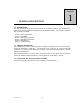
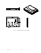
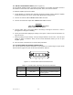
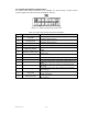
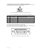
Table Of Contents

044-xxxxx Rev. x 2-4
2-7. DIFFERENTIAL IIC CLOCK, RECEIVE, AND TRANSMIT CONNECTOR P3
The alarms and sensing connections on the amplifier are made through a 6-pin micro-fit
connector (figure 2-3) and are listed and described in table 2-3.
Figure 2-3. Differential IIC Clock, Receive, and Transmit Connector P3
Table 2-3. Differential IIC Clock, Receive, and Transmit Connector P3 Definition
PIN SIGNAL DESCRIPTION
1 IIC_CLK+ Differential IIC Clock to the DPM
2 IIC_CLK- Differential IIC Clock to the DPM
3 IIC_RX_DATA+ Differential IIC Receive Data (from DPM)
4 IIC_RX_DATA- Differential IIC Receive Data (from DPM)
5 IIC_TX_DATA+ Differential IIC Transmit Data (to DPM)
6 IIC_TX_DATA- Differential IIC Transmit Data (to DPM)
2-8. IIC, POWER, ALARMS, AND CONTROLS CONNECTOR P4
The alarms and sensing connections on the amplifier are made through a 26-pin high density
D-Sub connector (figure 2-4) and are listed and described in table 2-4.
Figure 2-4. IIC, Power, Alarms, and Controls Connector P4