
User's Manual


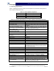


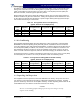
Table Of Contents

G3S-800-180-029 Installation & Service Manual
Copyright Powerwave Technologies, Inc., April 2002. All rights reserved
044-05112 Rev. A 2-1 April 2002
Section 2 Installation
2-1 Introduction
This section contains installation recommendations, unpacking, inspection, and installation in-
structions for the Multicarrier Cellular Amplifier. Carefully read all material in this section prior to
equipment unpacking or installation. Also read and review the operating procedures in Section 3
prior to installing the equipment. It is important that the licensee perform these tasks correctly and
in good faith. If applicable, carefully review the Federal Communications Commission (FCC) rules
as they apply to your installation. DON'T TAKE CHANCES WITH YOUR LICENSE.
2-2 Electrical Service Recommendations
Powerwave Technologies recommends that proper AC line conditioning and surge suppression
be provided on the primary AC input to the +27 Vdc power source. All electrical service should be
installed in accordance with the National Electrical Code, any applicable state or local codes, and
good engineering practice. Special consideration should be given to lightning protection of all
systems in view of the vulnerability of most transmitter sites to lightning. Lightning arrestors are
recommended in the service entrance. Straight, short ground runs are recommended. The elec-
trical service must be well grounded.
Each amplifier system should have its own circuit breaker, so a failure in one does not shut off the
whole installation. Circuit breakers should be capable of handling the anticipated inrush current, in
a load center with a master switch. Powerwave recommends that a 100 amp circuit breaker be
installed in the power distribution unit for each amplifier. DC wire smaller than 2 AWG 90°C cop-
per DC should not be installed. Each amplifier should have its own DC cable pair. See table 2-1.
CAUTION
This table and the foregoing are provided as guidelines. Follow the appropriate NEC
standards in your area and the cable manufacturer’s recommendation for proper cable
selection.
Table 2-1 Sample of DC Cable Ratings
AWG Copper Aluminum
or 3 Cond. In Raceway Single Conductor In Free Air 3 Cond. In Raceway Single Conductor In Free Air
MCM
90°C 110°C90°C 110°C 125°C 200°C90°C 110°C90°C 110°C 125°C 200°C
14 25 30 30 40 40 45 -- -- -- -- -- --
12 30 35 40 50 50 55 25 25 30 40 40 45
10 40 45 55 65 70 75 30 35 45 50 55 60
8 55 60 75 85 90 100 40 45 55 65 70 80
6 70 80 100 120 125 135 55 60 80 95 100 105
4 95 105 135 160 170 180 75 80 105 125 135 140
2 125 135 185 210 225 240 100 105 140 165 175 185
1 145 160 215 245 265 280 110 125 165 190 205 220
0 165 190 250 285 305 325 130 150 190 220 240 255
Based on ambient temperature of 30°C (86°F) 100% Load Factor
Source: Industrial Electric Wire & Cable Inc., Technical Guide Vol. 4M 11/99, Table III Suggested Ampacities - All Types
of Insulations; Based on National Electric Code