
User's Manual


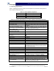


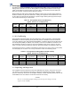
Table Of Contents

G3S-800-180-029 Installation & Service Manual
Copyright Powerwave Technologies, Inc., April 2002. All rights reserved
All specifications are subject to change without notice. Contact the factory for complete performance data.
044-05112 Rev. A
1-1 April 2002
Section 1 General Description
1-1 Introduction
This manual contains information and procedures for installation, operation, and maintenance of
Powerwave’s G3S-800-180-029 multicarrier cellular amplifier. The manual is organized into six
sections as follows:
Section 1. General Description
Section 2. Installation
Section 3. Operating Instructions
Section 4. Principles of Operation
Section 5. Maintenance
Section 6. Troubleshooting
1-2 General Description
The G3S-800-180-029 (see figure 1-1) is a linear, feed-forward power amplifier that operates in
the 25 MHz frequency band from 869 MHz to 894 MHz. The amplifier can simultaneously transmit
multiple frequencies, with better than -60 dBc third order intermodulation distortion (IMD). It is de-
signed for use in an amplifier system that is modular in design, and is ideally suited for use in
AMPS/TDMA/CDMA/CDPD/W-CDMA base stations. The plug-in Model G3S-800-180-029 ampli-
fier modules can each provide 180 watts of power nominally (210 W max.) and function com-
pletely independently of each other. The amplifier modules are designed for parallel operation to
produce high peak power output and system redundancy for remote applications, when installed
in multi-module amplifier subracks manufactured by Powerwave. All solid-state, the system is de-
signed to provide trouble-free operation with minimum maintenance. The system's modular con-
struction and unique and highly effective LED-based operational status and fault indicators help
minimize downtime. The turn-on and turn-off sequences of voltages are fully automatic, as is
overload protection and recycling. Inadvertent operator damage from front panel manipulation is
virtually impossible.
The amplifier module has a status connector that allows the host system to monitor the amplifier
module’s status. The front panel of each amplifier module has unit level status/fault indicators and
an RF on/off/reset switch. Primary power for the amplifier is +27 Vdc. Cooling for each plug-in
amplifier module is provided by four fans, two mounted on the front and two on the rear of the
module. The fans draw outside air through the front of the module and exhaust hot air out
through the rear of the module.
1-3 Functional And Physical Specifications
Functional and physical specifications for the amplifier are listed in table 1-2.
1-4 Equipment Changes
Powerwave Technologies, Inc. reserves the right to make minor changes to the equipment, in-
cluding but not necessarily limited to component substitution and circuitry changes. Changes that
impact this manual may subsequently be incorporated in a later revision of this manual.