
User's Manual


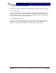
Table Of Contents

G3S-800-180-029 Installation & Service Manual
Copyright Powerwave Technologies, Inc., April 2002. All rights reserved
044-05112 Rev. A 5-3 April 2002
Unit Under Test
G3S-800-180
Plug-in
Amplifier
Module
+27 Vdc
Gnd RF In
RF
Out
20 dB
Directional Coupler
30 dB
Attenuator
500 W
20 dB
Attenuator
20 W
Power Meter
Sensor Head
8482A
1:2
Splitter
Power Meter
Sensor Head
8482A
Network Analyzer
8753C
Signal
Generator
Filter /
Isolator
Spectrum Analyzer
8651E
Figure 5-1 Amplifier System Test Setup Diagram
5-5.1.1 Amplifier IMD Test And Current Test
2. Adjust attenuator for an input signal at -10 dBm. Turn on the amplifier by setting RF ON
switch of amplifier. Adjust variable attenuator to set amplifier power output on power meter to
180 watts. Measure IMD on spectrum analyzer. IMD should be -60 dBc max. Record test
data in table 5-3. Set RF ON switch to OFF.
3. With the amplifier module set at 180 watts power output, use the current probe (magnetic
field type) and measure the dc current flow from the +27 Vdc power source. Current should
be 70 amps maximum. Record test data in table 5-3.
5-5.1.2 Gain Test
4. Disconnect spectrum analyzer from test setup, and connect the network analyzer.
5. Set network analyzer as follows:
Ø Power output to -10 dBm.
Ø Frequency start to 869 MHz.
Ø Frequency stop to 894 MHz.
Ø Normalize the network analyzer for gain and return loss.
6. Check the gain across the band from 869 MHz to 894 MHz. Gain should be between 58 dB.
Record test data in table 5-3.
5-5.1.3 Harmonics Test
7. With the power set at 180 watts power output, use the spectrum analyzer and check the fre-
quency band from 869 MHz to 894 MHz for harmonics. Harmonics should be 5 dBm maxi-
mum. Record test data in table 5-3.