
User's Manual
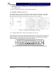

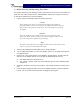


Table Of Contents

G3S-800-180-029 Installation & Service Manual
Copyright Powerwave Technologies, Inc., April 2002. All rights reserved
044-05112 Rev. A 4-2 April 2002
fied by a preamp and coupled to an attenuator and phase shifter in the first feed-forward loop.
The main signal is phase shifted by 180 degrees and amplified in the premain amplifier. The out-
put from the premain amplifier is fed to the class AB main amplifier. The output from the main
amplifier is typically 220 watts. The signal is output to several couplers and a delay structure.
The signal output from the main amplifier is sampled using a coupler, and the sample signal is
combined with the main input signal and input to the second feed-forward loop. The error signal is
attenuated, phase shifted 180 degrees, then fed to the error amplifier where it is amplified to a
level identical to the sampled output from the main amplifier. The output from the error amplifier
is then coupled back and added to the output from the main amplifier. The control loops continu-
ously make adjustments to cancel out any distortion in the final output signals.
Pre
Amp
Pre
Main
Main
Amp
Error
Amp
Delay
Feed Forward Loop control
2nd Loop
Phase & Gain
1st Loop
Phase & Gain
Delay
Alarms & Display
+15 +5 -5
Power Supply
-30dB
-10dB
RF Out
RFL
PWR
FWD
PWR
Front Panel
Smart Rack
+27VDC
Pre
Dist
Figure 4-1 G3S-800-180-029 Power Amplifier Module Functional Block Diagram
4-4.1 Main Amplifier
The input and output of the amplifier employ two-stage, class AB amplifiers which provide ap-
proximately 32 dB of gain in the 25 MHz frequency band from 869 to 894 MHz. The amplifier op-
erates on +27 Vdc, and a bias voltage of +5 Vdc, and is mounted directly on a heat sink that is
temperature monitored by a thermostat. If the heat sink temperature exceeds 90° C, a high tem-
perature fault occurs. The alarm logic controls the +5 Vdc bias voltage that shuts down the ampli-
fier.
4-4.2 Error Amplifier
The main function of the error amplifier is to amplify the distortion signal generated by the 1
st
Loop, to a level that cancels out the distortion and IMD when the error signal is coupled onto the
main signal at the amplifier output. The error amplifier is a balanced multistage, class AB ampli-
fier.
4-4.3 Amplifier Monitoring
In the main and error amplifier modules, all normal variations are automatically compensated for
by the feedforward loop control. However, when large variations occur beyond the adjustment
range of the loop control, a loop fault will occur. The alarms are displayed on the front panel indi-
cators and output via a 21-pin connector on the rear of the module to the subrack summary board