
User's Manual
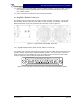
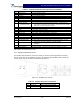


Table Of Contents

G3S-800-180-029 Installation & Service Manual
Copyright Powerwave Technologies, Inc., April 2002. All rights reserved
044-05112 Rev. A 4-1 April 2002
Section 4 Principles of Operation
4-1 Introduction
This section contains a functional description of the Multicarrier Cellular Amplifier.
4-2 RF Input Signal
This amplifier may be installed in a base station system as either a stand-alone module (i.e. in a
micro-cell application), or combined with multiple amplifiers in a combining subrack product avail-
able from Powerwave. In either case, the maximum input power for all carrier frequencies should
not exceed the limits specified in table 1-2. For proper amplifier loop balance and to ensure com-
pliance with FCC rules, the out of band components of the input signals should not exceed -40
dBc. The input VSWR presented to the amplifier should be 2:1 (or better) to maximize the transfer
of input power to the amplifier; this is particularly important when the amplifier is not installed in a
Powerwave manufactured combining subrack.
4-3 RF Output Load
The load impedance should be as good as possible (1.5:1 or better) in the working band for good
power transfer to the load. If the amplifier is operated into a filter, it will maintain its distortion
characteristics outside the signal band.
4-4 G3S-800-180-029 Amplifier Module
The G3S-800-180-029 amplifier is a linear, feed-forward power amplifier that operates in the 25
MHz frequency band from 869 MHz to 894 MHz. The amplifier modules are designed for parallel
operation to achieve high peak power output, and provide system redundancy when installed in
multi-module amplifier subracks manufactured by Powerwave. The Powerwave amplifier system
is ideally suited for unmanned remote locations.
The amplifier module, figure 4-1, has an average output of 180 watts nominal power (1800 watts
peak power) with intermodulation products suppressed to better than -60 dBc below carrier levels.
The amplifier provides an amplified output signal with constant gain and phase. Constant gain and
phase is maintained by continuously comparing active paths with passive references, and cor-
recting for small variations through the RF feedback controls. All gain and phase variations, for
example those due to temperature, are reduced to the passive reference variations. Each ampli-
fier module has an alarm and display board that monitors the amplifier performance. If a failure or
fault occurs in an amplifier module, it is displayed on the individual amplifier front panel.
The amplifier module is comprised of:
Predistorter
Pre-amplifiers
Main amplifier
Error amplifier
Two feed-forward loops with phase-shift and gain controls
DC/DC power regulator
Alarm monitoring, control and display panel
The main amplifier employs class AB amplification for maximum efficiency. The error amplifier
and feed forward loops are employed to correct signal nonlinearities introduced by the class AB
main amplifier. The error amplifier operates in class AB mode. The RF input signals are ampli-