
User's Manual

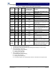


Table Of Contents

G3S-800-180-029 Installation & Service Manual
Copyright Powerwave Technologies, Inc., April 2002. All rights reserved
044-05112 Rev. A 3-4 April 2002
3-3 Initial Start-Up And Operating Procedures
The amplifier module has two operating controls, both located on the front face of the module: the
power ON - OFF switch and the RF ON - ON/OFF/RESET switch (refer to figures 1-1 and 3-1).
To perform the initial start-up, proceed as follows:
1. Verify that all input and output cables are properly connected.
CAUTION
Before applying power, make sure that the input and output of the amplifier are
properly terminated at 50 ohms. Do not operate the amplifier without a load attached.
Refer to table 1-2 for input power requirements. Excessive input power may damage
the amplifier
WARNING
Ensure the amplifier is turned off while disconnecting and reconnecting cables
between the antenna interface and power measurement equipment. Failure to do so
may cause damage to the equipment or personal injury.
NOTE
The output coaxial cable between the amplifier and the antenna must be 50 ohm coaxial
cable. Use of any other cable will distort the output.
2. Verify that the amplifier front panel switches are in the OFF position.
3. Turn on supply that provides +27 Vdc to the amplifier system. Do not apply an RF signal to
the amplifier system
4. Place the ON - OFF circuit breaker on the amplifier in the ON position. Visually check the
indicators on the amplifier module, and verify that the following indicators are on:
A. LPA DISAB. indicator (red) should be on.
B. The +27VDC, +15VDC, +5VDC and -5VDC indicators (green) on the amplifier module
should be on.
5. Set the RF ON switch to the ON (center) position. All red LEDs should turn off after six sec-
onds.
6. Follow the power setting procedure set forth in the amplifier subrack or system integration
manual. Turn on external exciter/transceiver and apply RF input signals.