
User's Manual
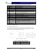

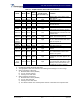


Table Of Contents

G3S-800-180-029 Installation & Service Manual
Copyright Powerwave Technologies, Inc., April 2002. All rights reserved
044-05112 Rev. A 3-2 April 2002
Reset (up position) - When toggled to reset position, all the red LED indicators will turn on
one at a time in sequence followed by all the green indicators one at a time in sequence; this
will also reset the fault latches. If the switch is held in the reset position, a microcontroller re-
set will occur. This will be verified by the LEDs toggling state again. The switch is spring
loaded to return to the normal ON position when released. If a fault occurs and the MCPA is
disabled, the alarms can be cleared and the MCPA enabled by this reset position. The func-
tions of the switch are disabled for five seconds after a power-up condition.
3-2.1.3 +27VDC Indicator
Green LED. When lit, indicates that the +27 Vdc supply is greater than +21 Vdc and less than
+31 Vdc. If the +27 Vdc indicator goes out, the DC FAIL indicator will illuminate. This indicates
that the +27 Vdc voltage dropped below +21 Vdc.
3-2.1.4 +15VDC Indicator
Green LED. When lit, indicates that the +15 Vdc supply is greater than +12 Vdc and less than
+17 Vdc. If the +15 Vdc indicator goes out, the DC FAIL indicator will illuminate. This indicates
that the +15 Vdc voltage dropped below +12 Vdc or increased above +17 Vdc.
3-2.1.5 +5VDC Indicator
Green LED. When lit, indicates that the +5 Vdc supply is greater than +2 Vdc and less than +7
Vdc. If the +5 Vdc indicator goes out, the DC FAIL indicator will illuminate. This indicates that the
+5 Vdc voltage dropped below +2 Vdc or increased above +7 Vdc.
3-2.1.6 -5VDC Indicator
Green LED. When lit, indicates that the -5 Vdc supply is greater than -7 Vdc and less than -2 Vdc.
If the -5 Vdc indicator goes out, the DC FAIL indicator will illuminate. This indicates that the -5
Vdc voltage dropped below -7 Vdc or increased above -2 Vdc.
3-2.2 Alarm Indicators
The alarm modes described here are indicative of amplifier alarm modes made to the amplifier
subrack. The amplifier subrack interprets these alarms and may subsequently deliver a different
alarm indication to the host equipment. Refer to the amplifier subrack manual to determine host
equipment level alarms.
Refer to section 6 to interpret and correct the various alarm states.
Refer to table 3-1.
A ‘Minor Alarm’ indicates a potential fatal amplifier problem via the amplifier front panel LEDs. and
the MCPA fault will be in evaluation.
A ‘Major Alarm’ indicates a major problem but the MCPA module will not be disabled.
A ‘Critical Alarm’ is indicative of a fatal problem. The fault indicator will latch on and the MCPA
module will be disabled.
Both ‘Major Alarm’ and ‘Critical Alarm’ will be sent to the host system via the MCPA subrack.