
User's Manual
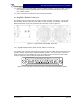
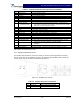

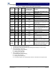


Table Of Contents

G3S-800-180-029 Installation & Service Manual
Copyright Powerwave Technologies, Inc., April 2002. All rights reserved
044-05112 Rev. A 3-1 April 2002
Section 3 Operating Instructions
3-1 Introduction
This section contains operating instructions for the Multicarrier Cellular Amplifier System.
3-2 Location And Function Of Amplifier Module Controls And Indicators
Primary +27 Vdc power is applied to the amplifier via a 100-amp circuit breaker (ON-OFF) located
on the left side of the amplifier front panel.
The plug-in amplifier module RF control and indicators, located in the center of the amplifier front
panel between the cooling fans, are shown in figure 3-1. The status and RF control functions and
alarms are described in detail in the subsequent paragraphs.
Figure 3-1 G3S-800-180-029 Amplifier Module RF Control and Indicators
3-2.1 Voltage Indicators And On/Off/Reset Switch
3-2.1.1 On Off Switch
This is the DC power switch for the amplifier module. The On/Off switch is a circuit breaker rated
for the inrush current and maximum current draw allowable with this amplifier module. This switch
should be in the Off position whenever the amplifier is inserted or removed from an amplifier
subrack.
3-2.1.2 RF ON Switch
Three position switch:
Off (down position) - Turns off RF section of amplifier module.
On (center position) - Normal amplifier on position.