
User's Manual
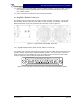
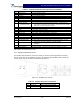

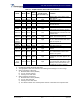


Table Of Contents

G3S-800-180-029 Installation & Service Manual
Copyright Powerwave Technologies, Inc., April 2002. All rights reserved
044-05112 Rev. A 2-5 April 2002
Table 2-4 Amplifier Module DC and Logic Connector Definition
Pin Function Description
A1 Power Input +27 Vdc (Power Contact)
A2 Power Input +27 Vdc (Power Contact)
A3 Ground Ground (Power Contact)
A4 Ground Ground (Power Contact)
1 RS485 +TxD Serial Communication Data Out
2 RS485 +RxD Serial Communication Data In
3 Service Loop TTL input to Amp. Gnd. for special test mode (Note 1)
4 MCPA Disabled
(Summary Fault)
TTL signal normally low indicates MCPA enabled. A high level indi-
cates that the MCPA has been disabled. Over Power, Over Voltage
takes one second to activate the signal.
5 Mod Addr 0 TTL input to Amp. Gnd. supplied by shelf to identify slot.
6 Mod Addr 1 TTL input to Amp. Gnd. supplied by shelf to identify slot.
7 TP1 TTL output. Future test point.
8 Manual Download GND to download manually
9 DC on stat TTL output. High indicates Amp is powered on.
10 RS485 –TxD Serial Communication Data Out
11 RS485 –RxD Serial Communication Data In
12 SCL7 No connection
13 SDA7 No connection
14 FP Disable Output Output, GND if the front panel switch is in the OFF position; +5 volts
indicates the front panel switch is in the ON position.
15 FP RST Output, GND if the front panel switch is in the RESET position; +5 volts
otherwise.
16 GND Ground
17 Module Detect Ground potential. Informs the subrack that an MCPA is plugged in.
Note 1: Service loop grounded allows the MCPA to be enabled or disabled by the front panel
switch when not mounted in the shelf.
2-6.2 Amplifier Module RF Connector
The amplifier has separate RF connectors, which are used for the RF signal input and output.
The RF connections on the amplifier connector are made through two BMA female coaxial con-
nectors (figure 2-3) and are listed and described in table 2-5.
Figure 2-3 Amplifier RF Connector
Table 2-5 Amplifier RF Connector Definition
Pin Function Description
A1 RF Input BMA Coaxial Female, Radiall
A2 RF Output BMA Coaxial Female, Radiall
A1
A2