869-894 MHz Installation & Service Manual G3S-800-140 Multi-Carrier Amplifier System 869 – 894 MHz 044-05095 Rev.
G3S-800-140 Installation & Service Manual © 2001 Powerwave Technologies Incorporated. All rights reserved. Powerwave Technologies, and the Powerwave logo are registered trademarks Powerwave Technologies, Inc. reserves the right to make changes to the documentation and equipment, including but not limited to component substitution and circuitry changes. Changes that impact this manual may subsequently be incorporated in a later revision of this manual. February 2001 Powerwave Technologies, Inc. 1801 E.
G3S-800-140 Installation & Service Manual Table Of Contents Par. No. 1-1 1-2 1-3 1-4 1-5 Section 1 General Description Page No. Introduction......................................................................................................................... 1-1 General Description ......................................................................................................... 1-1 Functional And Physical Specifications.......................................................................
G3S-800-140 Installation & Service Manual Section 5 Maintenance 5-1 5-2 5-3 5-4 5-5 5-5.1 5-5.2 5-5.3 5-5.4 5-5.5 5-5.6 5-6 5-6.1 5-6.2 Introduction......................................................................................................................... 5-1 Periodic Maintenance ...................................................................................................... 5-1 Test Equipment Required For Test.............................................................................
G3S-800-140 Installation & Service Manual List Of Tables Table No. 1-1 1-2 2-1 2-2 3-1 3-2 5-1 5-2 5-3 6-1 Major Amplifier Components .......................................................................................... 1-2 G3S-800-140 MCPA Functional Specifications ............................................................ 1-2 Amplifier Module DC and Logic Connector Definition............................................... 2-3 Amplifier RF Connector Definition ......................................
G3S-800-140 Installation & Service Manual Section 1 General Description 1-1 Introduction This manual contains information and procedures for installation, operation, and maintenance of Powerwave’s G3S-800-140 multicarrier cellular amplifier. The manual is organized into six sections as follows: Section 1. General Description Section 2. Installation Section 3. Operating Instructions Section 4. Principles of Operation Section 5. Maintenance Section 6.
G3S-800-140 Installation & Service Manual 1-5 Ordering Information Table 1-1 following gives the part numbers and descriptions to be used when ordering either an entire amplifier or replacement fans. Table 1-1 Major Amplifier Components Model number G3S-800-140 800-01075-003 800-00972-002 Description 140 W 869-894 MHz MCPA Module. Front fan assembly Rear fan assembly.
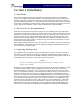
G3S-800-140 Installation & Service Manual Figure 1-1 G3S-800-140 044-05095 Rev.
G3S-800-140 Installation & Service Manual Section 2 Installation 2-1 Introduction This section contains installation recommendations, unpacking, inspection, and installation instructions for the Multicarrier Cellular Amplifier. Carefully read all material in this section prior to equipment unpacking or installation. Also read and review the operating procedures in Section 3 prior to installing the equipment. It is important that the licensee perform these tasks correctly and in good faith.
G3S-800-140 Installation & Service Manual 2-4 Installation Instructions (refer to figures 1-1 and 2-1) The G3S-800-140 amplifier module is designed for installation in a subrack that permits access to the rear of the subrack for connection of DC power, RF, and monitor cables. To install the amplifier proceed as follows: 1. Install subrack in equipment rack and secure in place. 2. Connect antenna cable to rear of subrack. 3. Connect the transceiver output(s) to rear of subrack. 4.
G3S-800-140 Installation & Service Manual 2-5.1 Amplifier Module Status, Alarm, Control, And Power Connector The amplifier has a separate remote alarm and control connector which may be used by the host system to monitor and control the individual amplifier modules. The status, alarm, control, and power connections on the amplifier connector are made through a 21-pin male D-Sub combo connector (figure 2-2) and are listed and described in table 2-1.
G3S-800-140 Installation & Service Manual 2-5.2 Amplifier Module RF Connector The amplifier has a separate RF connector which is used for the RF signal input and output. The RF connections on the amplifier connector are made through two BMA female coaxial connectors (figure 2-3) and are listed and described in table 2-2. A1 A2 Figure 2-3 Amplifier RF Connector Table 2-2 Amplifier RF Connector Definition Pin A1 A2 044-05095 Rev.
G3S-800-140 Installation & Service Manual Section 3 Operating Instructions 3-1 Introduction This section contains operating instructions for the Multicarrier Cellular Amplifier System. 3-2 Location And Function Of Amplifier Module Controls And Indicators Primary +27 Vdc power is applied to the amplifier via a 100-amp circuit breaker (ON-OFF) located on the left side of the amplifier front panel.
G3S-800-140 Installation & Service Manual Table 3-1 Amplifier Module RF Control and Indicators Definition Name Function (Note: MCPA = Multicarrier Power Amplifier) +27VDC Green LED. When lit, indicates that the +27 Vdc supply is greater than +21 Vdc and less than +31 Vdc. If the +27 Vdc indicator goes out, the DC FAIL indicator will illuminate. This indicates that the +27 Vdc voltage dropped below +21 Vdc. Indicator +15VDC Indicator Green LED.
G3S-800-140 Installation & Service Manual A ‘Minor Alarm’ will flag a potential fatal problem by the LEDs and the MCPA fault will be in evaluation. A ‘Critical Alarm’ is indicative of a fatal problem. The fault indicator will latch on and the MCPA module will be disabled. A ‘Major Alarm’ indicates a major problem but the MCPA module will not be disabled. Both ‘Major Alarm’ and ‘Critical Alarm’ will be sent to the host system via the MCPA subrack.
G3S-800-140 Installation & Service Manual 3-3 Initial Start-Up And Operating Procedures The amplifier module has two operating controls, both located on the front face of the module: the power ON - OFF switch and the RF ON - ON/OFF/RESET switch. To perform the initial start-up, proceed as follows: 1. Double check to ensure that all input and output cables are properly connected. CAUTION Before applying power, make sure that the input and output of the amplifier are properly terminated at 50 ohms.
G3S-800-140 Installation & Service Manual Section 4 Principles of Operation 4-1 Introduction This section contains a functional description of the Multicarrier Cellular Amplifier. 4-2 RF Input Signal The maximum input power for all carrier frequencies should not exceed the limits specified in table 1-2. For proper amplifier loop balance, the out of band components of the input signals should not exceed -40 dBc. The input VSWR should be 2:1 maximum (or better).
G3S-800-140 Installation & Service Manual attenuated, phase shifted 180 degrees, then fed to the error amplifier where it is amplified to a level identical to the sampled output from the main amplifier. The output from the error amplifier is then coupled back and added to the output from the main amplifier. The control loops continuously make adjustments to cancel out any distortion in the final output signals.
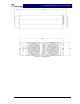
G3S-800-140 Installation & Service Manual 4-4.4 Amplifier Module Cooling Although each amplifier module contains its own heat sink, it is cooled with forced air. Four fans are used for forced air cooling and redundancy. The fans, located on the front and rear of the amplifier module, draw air in through the front of the amplifier and exhaust hot air out the back of the module. The fans are field replaceable.
G3S-800-140 Installation & Service Manual Section 5 Maintenance 5-1 Introduction This section contains periodic maintenance and performance test procedures for the Multicarrier Cellular Amplifier. It also contains a list of test equipment required to perform the identified tasks. NOTE Check your sales order and equipment warranty before attempting to service or repair the unit. Do not break the seals on equipment under warranty or the warranty will be null and void.
G3S-800-140 Installation & Service Manual Table 5-2 Test Equipment Required Nomenclature Signal Generator 30 dB Attenuator, 500 Watt 20 dB Attenuator, 20 Watt (2 each) Spectrum Analyzer Coax Directional Coupler Power Meter/Sensor Network Analyzer Current Probe Manufacturer RDL Weinschel Corp. Tenuline Model IMD-801D-03A 53-30-34 H.P. H.P. H.P. H.P. 8560E 778D 437B/8481A 8753C 5-4 Cleaning Air Inlets/Outlets The air inlets and outlets should be cleaned every 30 days.
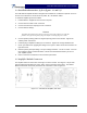
G3S-800-140 Installation & Service Manual Unit Under Test +27 Vdc Gnd G3S-800-140 Plug-in Amplifier Module RF Out 30 dB Attenuator 20 dB Directionl Coupler 20 dB Attenuator 500 W 20 W Power Meter RF In 20 W 20 dB Attenuator Directionl Coupler Spectrum Analyzer 8651E Sensor Head 8482A Network Analyzer 8753C Filter / Isotlator Signal Generator 10 dB Variable Attenuator Sensor Head 8482A Power Meter Figure 5-1 Amplifier System Test Setup Diagram 5-5.2 Amplifier IMD Test And Current Test 2.
G3S-800-140 Installation & Service Manual 5-5.5 Spurious Test 8. 5-5.6 9. With the power amplifier set at 140 watts power output, use the spectrum analyzer and check the frequency band from 869 MHz to 894 MHz for spurious signals. Spurious signals should be -60 dBc maximum. Record test data in table 5-3. Input Return Loss Test Reset and turn on amplifier module. Read and record the S11 return loss measurement on network analyzer. Input return loss should be –16 dB maximum. Record test data in table 5-3.
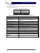
G3S-800-140 Installation & Service Manual Table 5-3 Multicarrier Cellular Amplifier Test Data Sheet DATE _________________________________ AMPLIFIER S/N _________________________ TEST CONDITIONS: Load and Source Impedance: 50 Ohms VSWR: < 1.2:1 Supply Voltage: +27 Vdc ±1.0 Vdc TEST 4-TONE IMD RF Gain Gain Flatness Harmonics Spurious Input Return Loss DC Power SPECIFICATION Vcc = 27 Vdc PO = 140 W Freq.: 880, 883, 886, and 889 MHz Vcc = 27 Vdc PO = 140 W Freq.
G3S-800-140 Installation & Service Manual 5-6 Field Replaceable Parts And Modules The following parts and modules can be replaced in the field on site by a qualified technician with experience maintaining RF power amplifiers and similar equipment: 1. G3S-800-140 power amplifier modules 2. Cooling fans 5-6.1 G3S-800-140 Power Amplifier Module To replace a power amplifier module, proceed as follows: 1.
G3S-800-140 Installation & Service Manual Section 6 Troubleshooting 6-1 Introduction This section contains a list of problems which users have encountered and a few suggested actions that may correct the problem. If the suggested corrective action does not eliminate the problem, please contact your Powerwave field representative or the factory for further instructions. NOTE Check your sales order and equipment warranty before attempting to service or repair the unit.