
User's Manual
044-05077 Rev. A
3-4
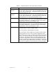
4. When overpower is detected:
a) MCPA shall shut down (disable)
b) Turn on Over Pwr LED
c) Set flag for Over Pwr alarm
d) The MCPA module shall use a peak power detector to determine the overpower fault.
3-3. INITIAL START-UP AND OPERATING PROCEDURES
The amplifier module has two operating controls, both located on the front face of the module: the
power ON - OFF switch and the RF ON - ON/OFF/RESET switch. To perform the initial start-up,
proceed as follows:
1. Double check to ensure that all input and output cables are properly connected.
CAUTION
Before applying power, make sure that the input and output of the
amplifier are properly terminated at 50 ohms. Do not operate the
amplifier without a load attached. Refer to table 1-2 for input
power requirements. Excessive input power may damage the am-
plifier
NOTE
The output coaxial cable between the amplifier and the antenna must
be 50 ohm coaxial cable. Use of any other cable will distort the output.
2. Verify that the amplifier front panel switches are in the OFF position.
3. Turn on supply that provides +27 Vdc to the amplifier system. Do not apply an RF
signal to the amplifier system
4. Place the ON - OFF circuit breaker on the amplifier in the ON position. Visually check
the indicators on the amplifier module, and verify that the following indicators are on:
a. LPA DISAB. indicator (red) should be on.
b. The +27VDC, +15VDC, +5VDC and -5VDC indicators (green) on the amplifier
module should be on.
5. Set the RF ON switch to the ON (center) position. All red LEDs should turn off after
six seconds.
6. Turn on external exciter/transceiver and apply RF input signals.