
User's Manual

044-05077 Rev. A
3-3
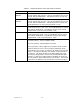
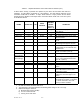
Table 3-1. Amplifier Module RF Control and Indicators Definition (cont.)
A ‘Minor Alarm’ will flag a potential fatal problem by the LEDs and the MCPA fault will be in
evaluation. A ‘Critical Alarm’ is indicative of a fatal problem. The fault indicator will latch on and
the MCPA module will be disabled. A ‘Major Alarm’ indicates a major problem but the MCPA
module will not be disabled. Both ‘Major Alarm’ and ‘Critical Alarm’ will be sent to the host system
via the MCPA subrack.
ALARM CATEGORY LED
MCPA
MODULE
MCPA
DISABLE
SIGNAL
(Pin 4 in
Table 2-1)
CONDITION
Over Pwr Critical Red Disable High MCPA module output power >110
watts (Note 4)
Over Pwr Critical Red Disable High Input power >-3 dBm
High Temp Minor Red Enable Low High temperature detected
High Temp Critical Red Disable High High temperature detected for longer
than two minutes
VSWR Minor Red Enable Low Reflected power detected at output
>12 W
VSWR Critical Red Disable High Reflected power detected at output
>50 W longer than approx. two min.
DC Fail Minor Red Enable Low One of the internal DC voltages
dropped below or exceeded the safe
threshold level
DC Fail Critical Red Disable High Voltage out of range for longer than
approx. two minutes (Note 2)
DC Fail
(Over voltage)
Minor Red Disable Low +27 Vdc input >31 V detected (note
3)
DC Fail
(Over voltage)
Critical Red Disable High +27 Vdc input >30 V for longer than
one sec. after initial detection of DC
input >31 V (Note 3)
Fan Fail (one) Major Red Enable Low Any fan failure
Loop Fail Minor Red Enable Low Loop failure detected
Loop Fail Critical Red Disable High Loop failure detected longer than two
minutes
Low Pwr Minor Red Enable Low Rack controller detected MCPA out-
put is 3 dB below that of the other
MCPA in the system.
Low Pwr Critical Red Disable High Rack controller detected low power
condition for more than approx. two
minutes
LPA DISAB. Critical Red Disable High Unit is manually switched off using the
front panel RF ON switch, or disabled
by a serial command or auto shut-
down by an alarm condition.
NOTES:
1. RS-485 serial alarm will follow LED status.
2. The appropriate status LED shall turn off indicating which voltage is out of its range.
3. When overvoltage is detected:
a) MCPA shall shut down (disable)
b) Turn on red DC Fail LED
c) Set flag for DC Fail alarm