
User's Manual

044-05077 Rev. A
3-2
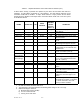
Table 3-1. Amplifier Module RF Control and Indicators Definition
NAME FUNCTION (Note: MCPA = Multicarrier Power Amplifier)
+27VDC
Indicator
Green LED. When lit, indicates that the +27 Vdc supply is greater than
+21 Vdc and less than +31 Vdc. If the +27 Vdc indicator goes out, the
DC FAIL indicator will illuminate. This indicates that the +27 Vdc volt-
age dropped below +21 Vdc.
+15VDC
Indicator
Green LED. When lit, indicates that the +15 Vdc supply is greater than
+12 Vdc and less than +17 Vdc. If the +15 Vdc indicator goes out, the
DC FAIL indicator will illuminate. This indicates that the +15 Vdc volt-
age dropped below +12 Vdc or increased above +17 Vdc.
+5VDC Indicator Green LED. When lit, indicates that the +5 Vdc supply is greater than
+2 Vdc and less than +7 Vdc. If the +5 Vdc indicator goes out, the DC
FAIL indicator will illuminate. This indicates that the +5 Vdc voltage
dropped below +2 Vdc or increased above +7 Vdc.
-5VDC Indicator Green LED. When lit, indicates that the -5 Vdc supply is greater than
-7 Vdc and less than -2 Vdc. If the -5 Vdc indicator goes out, the DC
FAIL indicator will illuminate. This indicates that the -5 Vdc voltage
dropped below -7 Vdc or increased above -2 Vdc.
RF ON Switch Three position switch:
Off (down position) - Turns off amplifier module.
On (center position) - Normal amplifier on position.
Reset (up position) - When toggled to reset position, all the red LED
indicators will turn on one at a time in sequence followed by all the
green indicators one at a time in sequence; this will also reset the fault
latches. If the switch is held in the reset position, a microcontroller re-
set will occur. This will be verified by the LEDs toggling state again.
The switch is spring loaded to return to the normal ON position when
released. If a fault occurs and the MCPA is disabled, the alarms can
be cleared and the MCPA enabled by this reset position. The functions
of the switch are disabled for five seconds after a power-up condition.