
User's Manual


044-05077 Rev. A
2-2
2-4. INSTALLATION INSTRUCTIONS (Refer to figures 1-1 and 2-1)
The G3S-1900-80 amplifier module is designed for installation in a subrack that permits access to
the rear of the subrack for connection of DC power, RF, and monitor cables.
To install the amplifier proceed as follows:
1. Install subrack in equipment rack and secure in place.
2. Connect antenna cable to rear of subrack.
3. Connect the transceiver output(s) to rear of subrack.
4. Connect alarms cable(s).
WARNING
Verify that all circuit breaker switches on the rear
panel of the subrack are in the OFF position. Turn
off external primary DC power before connecting DC
power cables.
7. Connect positive primary power and negative primary power to the subrack. Tighten the
subrack power connections.
8. Install the plug-in amplifier module(s) in the subrack. Verify that the latch is properly seated.
9. Check your work before applying DC voltage to the system. Make certain all connections are
tight and correct.
10. Measure primary DC input voltage. DC input voltage should be +27 Vdc ±1.0 Vdc. If the DC
input voltage is above or below the limits, call and consult Powerwave before you turn on your
amplifier system.
11. Refer to section 3 for initial turn-on and checkout procedures.
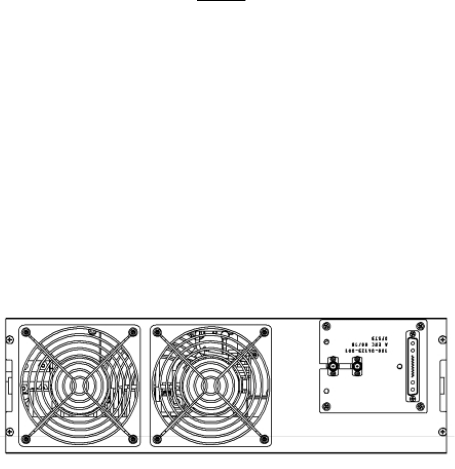
2-5 AMPLIFIER MODULE CONNECTORS
The amplifier has three connectors on the right rear of the module. The largest is a 21-pin male
D-Sub combo which provides the status, alarm, control, and power connections. The smaller
connectors are BMA female coaxial contacts from Radiall, which provide the RF connections.
Refer to figure 2-1.
Figure 2-1. G3S-1900-80 Amplifier, Rear View