ConnectUPSZ WEB/SNMP Card User’s Guide X and BD Models www.powerware.
Class B EMC Statements FCC Part 15 NOTE This equipment has been tested and found to comply with the limits for a Class B digital device, pursuant to part 15 of the FCC Rules. These limits are designed to provide reasonable protection against harmful interference in a residential installation. This equipment generates, uses and can radiate radio frequency energy and, if not installed and used in accordance with the instructions, may cause harmful interference to radio communications.
Requesting a Declaration of Conformity Units that are labeled with a CE mark comply with the following harmonized standards and EU directives: : : Harmonized Standards: EN 50091-1-1 and EN 50091-2; IEC 950 Second Edition, Amendments A1, A2, A3, and A4 EU Directives: 73/23/EEC, Council Directive on equipment designed for use within certain voltage limits 93/68/EEC, Amending Directive 73/23/EEC 89/336/EEC, Council Directive relating to electromagnetic compatibility 92/31/EEC, Amending Directive 89/336/EEC r
TABLE OF CONTENTS 1 Introduction . . . . . . . . . . . . . . . . . . . . . . . . . . . . . . . . . . . . . . 1 System Application . . . . . . . . . . . . . . . . . . . . . . . . . . . . . . . . . . . . . . . . . . . . 3 2 Installation . . . . . . . . . . . . . . . . . . . . . . . . . . . . . . . . . . . . . . . 5 ConnectUPS Web/SNMP Card Front Panels . . . . . . . . . . . . . . . . . . . . . . . . . . . LED Description . . . . . . . . . . . . . . . . . . . . . . . . . . . . . . . . . . . . . . . . . . . .
Table of Contents Becoming a Superuser . . . . . . . . . . . . . . . . . . . . . . . . . . . . . . . . . . . . . . . Turning the UPS On and Off . . . . . . . . . . . . . . . . . . . . . . . . . . . . . . . . . . . . Forcing the UPS to Shut Down . . . . . . . . . . . . . . . . . . . . . . . . . . . . . . . . . . Planning a Scheduled UPS Shutdown and Restart . . . . . . . . . . . . . . . . . . . . Configuring E-mail Notification . . . . . . . . . . . . . . . . . . . . . . . . . . . . . . . . .
CHAPTER 1 INTRODUCTION The ConnectUPSZ Web/SNMP Card is a network card for your uninterruptible power system (UPS) that provides both SNMP and HTTP compatibility. You can install the card in any Powerware9 UPS that has an X-SlotZ or a BestDockZ slot. The ConnectUPS Web/SNMP Card is available in two models: the ConnectUPS-X for X-Slot UPSs and the ConnectUPS-BD for UPSs with a BestDock slot. Both models can connect to a twisted-pair Ethernet (10/100BaseT) network using an RJ-45 connector.
Introduction In addition, the ConnectUPS Web/SNMP Card has the following features: : Hot-swappable feature simplifies installation by allowing you to install the card safely without powering down the critical UPS load. : Configuration from serial port, Telnet, or HTTP Web browser. : Management from HTTP Web browser, Internet-ready cell phone or PDA, or SNMP management software.
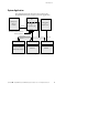
Introduction System Application The following diagram shows how the ConnectUPS Web/SNMP Card can be used in a network application. UPS Management Station or Terminal RS-232 ConnectUPS-X or ConnectUPS-BD NMS Station or Web Browser Additional network connections with ConnectUPS-X Power Line Ethernet NetWatch Client NetWatch Client NetWatch Client Microsoft Windows 95/98/Me/NT/2000/XP UNIX/Linux NetWare Figure 1.
Introduction 4 ConnectUPS Z Web/SNMP Card (X and BD Models) User’s Guide : Rev A www.powerware.
CHAPTER 2 INSTALLATION With the hot-swappable feature, the ConnectUPS Web/SNMP Card can be installed easily without turning off the UPS or disconnecting the load. To install the ConnectUPS Web/SNMP Card, perform the following steps: 1. Verify that both DIP switches on the card are set to the 0 (off) position. 2. Remove the X-Slot or BestDock cover on the UPS rear panel. Retain the screws.
Installation ConnectUPS Web/SNMP Card Front Panels The card panel details are shown in Figure 2 and Figure 3. Uplink Ethernet Connector 10 Mb Network LEDs (yellow) Power LED (green) Status LED (yellow) 100 Mb Network LEDs (green) Off DIP Switch 1 2 On Additional Ethernet Connectors COM Port Reset Button Figure 2.
Installation LED Description The functions of the ConnectUPS Web/SNMP Card are indicated by the Status and either the 10 Mb or 100 Mb LEDs, as listed in Table 1. Table 1.
Installation Configuring the Card Remotely You can configure the card remotely through a network using a Web browser or Telnet utility. NOTE Security-related parameters and some hardware parameters cannot be configured from a Web browser, but can be changed from the Telnet utility. If you choose to configure your card remotely, see “Remote Configuration” on page 17. 8 ConnectUPS Z Web/SNMP Card (X and BD Models) User’s Guide : Rev A www.powerware.
CHAPTER 3 LOCAL CONFIGURATION Use the following procedure to access the card’s configuration program through a serial port. Before You Start To use the configuration program for the card, you need: : The serial cable included with the card. : A terminal with a serial communication port, or a computer with a terminal emulation program such as HyperTerminal9. The serial line should be set to 9600 baud, No parity, 8 data bits, 1 stop bit, and no flow control.
Local Configuration 3. Open your terminal emulation program such as HyperTerminal and select the appropriate serial connection (such as COM1). The serial line should be set to 9600 baud, No parity, 8 data bits, 1 stop bit, and no flow control. 4. Verify that the UPS is turned on. 5. After a few seconds, press [Enter]. The Password screen appears (see Figure 5). If the screen does not appear, press [Enter] again.
Local Configuration Configuring the Card To configure the card: 1. Type 1 to enter the Web/SNMP Card Settings screen (see Figure 6). +=================================================================== | [ ConnectUPS Web/SNMP Card Configuration Utility ] +=================================================================== 1. Web/SNMP Card Settings 2. Reset Configuration to default 3. Restart Web/SNMP Card 4. UPS Pass-Through 0.
Local Configuration 3. Change any other options as needed for your particular configuration by typing the corresponding number shown in the menu (2 through 10). Each setting is described in the following sections. 4. Type 0 to return to the Main Menu. 5. Type 0 to exit the ConnectUPS Web/SNMP Card configuration. The ConnectUPS Web/SNMP Card automatically saves all settings after exiting the configuration function (see Figure 7).
Local Configuration +=================================================================== | [ ConnectUPS Web/SNMP Card Configuration Utility ] +=================================================================== 1. Set the IP Address, Gateway Address and MIB System Group 2. Set Web/SNMP Card Control Group 3. Set Write Access Managers 4. Set Trap Receivers 5. Set IP Addresses of Primary and Secondary Date Server 6. UPS Event Actions 7. Set UPS information 8. Set Superuser Name and Password 9.
Local Configuration Set the IP Address, Gateway Address and MIB System Group Use this function (option 1) to set the IP address, the gateway address, or the management information base (MIB) parameters of the card, as listed in Table 2. Table 2. Parameters with Examples No. Function Description Example 1 IP Address IP address of the card 192.72.173.188 2 Gateway Address Default IP address of the network gateway 192.72.173.254 3 Network Mask Subnet mask setting 255.255.255.
Local Configuration Set Write Access Managers For those users who intend to use an SNMP-compatible NMS to manage the ConnectUPS Web/SNMP Card, the IP address of the management station must be added to the list on the ConnectUPS Web/SNMP Card in order to receive read (get) or write (set) access rights. Community strings may be different for read or write access. Use this function to add or delete the IP address of the management station (option 3).
Local Configuration Set UPS Information Use this function to enter additional information about the UPS including date of installation and date of last battery replacement (option 7). In addition, set timing values relating to the shutdown and restart of the UPS via this function. This information is accessible via the HTTP interface for easy modification after the card is on the network.
CHAPTER 4 REMOTE CONFIGURATION Use the following procedure to access the card’s configuration program through a Web browser. NOTE Verify that an active 10/100BaseT cable is connected to the card’s network connector (the Uplink Ethernet connector on the ConnectUPS-X). Add a Routing Condition in the Computer If the IP address of the computer is on the same network with the ConnectUPS Web/SNMP Card, you may just run the Web browser directly.
Remote Configuration Running the Web Browser Locate a computer (PC, host, or server) that has a Web browser (Internet Explorer or Netscape recommended) and is connected to a network. 1. Run the Web browser and connect to the ConnectUPS Web/SNMP Card IP address (the default is 192.168.7.18). 2. The home page of the ConnectUPS Web/SNMP Card appears (see Figure 8). Figure 8. ConnectUPS Web/SNMP Card Home Page 18 ConnectUPS Z Web/SNMP Card (X and BD Models) User’s Guide : Rev A www.powerware.
Remote Configuration Setup Network Configuration 1. Select Configuration from the menu at the top of the home page, then Web/SNMP Card Configuration to set the ConnectUPS Web/SNMP Card parameters (see Figure 9). 2. Click Become Superuser and log in with the Username and Password (the default user name and password is admin). Figure 9. ConnectUPS Web/SNMP Card Configuration Page ConnectUPS Z Web/SNMP Card (X and BD Models) User’s Guide : Rev A www.powerware.
Remote Configuration 3. Select and edit the ConnectUPS Web/SNMP Card IP Address. 4. Select and edit the Gateway Address for the network. 5. Select and edit the Subnet Mask of the network. 6. Select Set Values to save the new settings. NOTE If you changed the IP address in Step 3, you must restart the browser using the new IP address (see page 18) to restore communication with the ConnectUPS Web/SNMP Card. Repeat Steps 1 and 2 to continue the configuration. 7.
CHAPTER 5 UPS POWER MANAGEMENT You can manage the UPS from a Web browser or from an SNMP network management system. UPS Management from a Web Browser When using a Web browser to access the ConnectUPS Web/SNMP Card, the majority of UPS-related information is available by selecting any of the following menu options: : : : : : : : Identification UPS Monitoring UPS History Configuration Control Registered Clients Help Each menu and submenu selection has online help available.
UPS Power Management If you leave the browser pointed to this page, it automatically updates when new UPS information is available. To return to the UPS Status page, point and click the mouse pointer anywhere within the colored background area. ConnectUPS MultiView Software The Status@aGlance pages of several ConnectUPS Web/SNMP Cards may be monitored simultaneously by installing the ConnectUPS MultiView software on a PC with Microsoft Windows 95/98/Me/NT/2000/XP.
UPS Power Management Turning the UPS On and Off The ConnectUPS Web/SNMP Card supports the ability to remotely turn off the UPS and its supported load. It also supports the ability to reboot the UPS (cycling output power off and then back on), as well as the ability to schedule shutdowns and startups on a predetermined basis. Selecting Control from the menu at the top of the home page provides a page that allows the Superuser to turn off the UPS.
UPS Power Management 6. To turn off the UPS and have it stay off (requiring local interaction to turn it back on), change Load Segment to Restart following the return of AC Line to NO. If you want to effectively reboot the UPS and the associated load, then set Load Segment to Restart following the return of AC Line to YES and set Delay Before Segment Restart to a valid delay value to allow the UPS to restart after the specified delay. 7.
UPS Power Management 6. Then select Enable UPS Shutdown Schedule, followed by Set Values to start the process. Any shutdown/restart events repeat until you change the table or select Disable UPS Shutdown Schedule. NOTE Before scheduling any shutdowns or startups, you must configure the date and time within the ConnectUPS Web/SNMP Card.
UPS Power Management page with your browser. This is especially helpful if you have more than one ConnectUPS Web/SNMP Card and intend to receive e-mails at a central location. If your SMTP server requires a qualified domain name instead of an IP address or requires a qualified user name in the sender’s email address, additional configuration items are available with a serial or Telnet connection (see Chapter 3, “Local Configuration” on page 9).
UPS Power Management Performing a Manual UPS Battery Test You can use the ConnectUPS Web/SNMP Card to manually perform a UPS battery test. The ability to test the UPS is model dependent (consult your UPS documentation for more information). 1. To manually start a battery test on a specific UPS, select Control from the menu at the top of the home page. 2. Become a Superuser and then select Initiate Battery Test, followed by Set Values to start the process.
UPS Power Management 2. The xups.mib and stdupsv1.mib files (on the supplied CD-ROM) contain the MIB for the ConnectUPS Web/SNMP Card. Add these files to the MIB database of your SNMP management software (such as HP OpenViewZ , IBM9 Director, and Sun NetManager). 3. Using the Facilities provided by the SNMP management software, you can access the individual MIB objects. Refer to the MIB files on the supplied CD-ROM for more information.
UPS Power Management Automatic Shutdown of UPS-Protected Computers NetWatch client software supports remote UPS monitoring and automatic shutdown of UPS-protected computer systems and is available on the supplied CD-ROM or from www.powerware.com.
UPS Power Management 30 ConnectUPS Z Web/SNMP Card (X and BD Models) User’s Guide : Rev A www.powerware.
APPENDIX The appendix contains the card specifications, DIP switch and jumper settings, upgrading the firmware, service and support, and the warranty. Table 3.
Appendix DIP Switch Description DIP switch definitions for both types of the ConnectUPS Web/SNMP Cards are listed in Table 4. Table 4. DIP Switch Modes SW1 SW2 Description Off Off Operational Mode (default) Off On BOOTP/DHCP Enable Mode (overrides the serial/Telnet configuration) On Off Reserved On On Reserved Jumper 1 (JP1) Settings The JP1 jumper is found on both the ConnectUPS-X and ConnectUPS-BD. The JP1 pins are NOT jumpered by factory-default. Table 5 shows the jumper definitions.
Appendix Upgrading the Card Firmware During the upgrade process, the ConnectUPS Web/SNMP Card is inaccessible, but restarts automatically within a minute after completing the upgrade. To upgrade the ConnectUPS-X or ConnectUPS-BD firmware, use the following steps: 1. Locate a networked PC with Microsoft Windows 95/98/Me/NT/2000/XP. 2. Copy the supplied Firmware Upgrade Utility (upgrade100.exe) program to the PC. 3.
Appendix 6. Highlight the ConnectUPS Web/SNMP Card IP address to select the individual card. Click Modify and enter the Superuser name and password. Repeat this step for each card that will be upgraded. 7. Select Open next to Filename and select the binary upgrade file that was previously downloaded or otherwise received and copied to the PC. Select Upgrade to start the process. After the process starts, do not cancel or interrupt the upgrade process.
Appendix If repair is required, you will be given a Returned Material Authorization (RMA) Number. This number must appear on the outside of the package and on the Bill Of Lading (if applicable). Use the original packaging or request packaging from the Help Desk or distributor. Units damaged in shipment as a result of improper packaging are not covered under warranty. A replacement or repair unit will be shipped, freight prepaid for all warrantied units.
Appendix Extended Service Coverage A full complement of warranty extensions and enhancements are available from Powerware Corporation for your UPS. Information pertaining to these services should be available in the shipping container along with this manual. If not, or if you would like more information, call the Powerware Corporation Help Desk and ask about warranty services.