Online UPS PowerWalker VFI 6000T LCD (L) PowerWalker VFI 10000T LCD (L) Manual (EN) Uninterruptible Power Supply System
CONTENT: 1. Safety and EMC Instructions .............................................................. 1 1.1 Installation ....................................................................................... 1 1.2 Operation ......................................................................................... 2 1.3 Maintenance, Servicing and Faults ................................................. 2 1.4 Transport .........................................................................................
7.3 Trouble Shooting In Else Cases .................................................... 50 8. Battery Maintenance .......................................................................... 51 9. Communication Port .......................................................................... 52 9.1 USB Interface ................................................................................ 52 9.2 Dry contact Interface ..................................................................... 52 9.
1. Safety and EMC Instructions Please read carefully the following user manual and the safety instructions before installing the unit or using the unit! 1.1 Installation This is permanently connected equipment, and it must be installed by qualified maintenance personnel. Condensation may occur if the UPS is moved directly from a cold to a warm environment. The UPS must be absolutely dry before being installed. Please allow an acclimatization time of at least two hours.
With the installation of the equipment, the sum of the leakage current of the UPS and the connected load does not exceed 5% of rated value of input current. Do not block ventilation openings in the UPS’s housing. Ensure allow at least 50cm of space on front and rear of the UPS. 1.2 Operation Do not disconnect the mains cable on the UPS or the building wiring terminals during operation since this would remove the protective earth from the UPS and all connected loads.
Before carrying out any kind of service and/or maintenance, isolate UPS and disconnect the batteries. Verify that no current is present and no hazardous voltage exists in the capacitor or BUS capacitor. Batteries must be replaced only by qualified personnel. Batteries have a high short-circuit current and pose a risk of shock.
1.6 Standards * Safety IEC/EN 62040-1 * EMI Conducted Emission..........................:IEC/EN 62040-2 Category C3 Radiated Emission.............................:IEC/EN 62040-2 Category C3 * EMS ESD...................................................:IEC/EN 61000-4-2 Level 3 RS.....................................................:IEC/EN 61000-4-3 Level 3 EFT....................................................:IEC/EN 61000-4-4 Level 4 SURGE..............................................
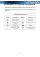
2. Description of Commonly Used Symbols Some or all of the following symbols may be used in this manual.
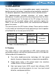
3. Introduction This On-Line series is an uninterruptible power supply incorporating double-converter technology. It provides perfect protection specifically for computer equipments, communication servers, and data centers. The double-converter principle eliminates all mains power disturbances. A rectifier converts the alternating current from the mains power to direct current. On the basis of this DC voltage, the inverter generates an AC sinusoidal voltage, which constantly supplies the loads.
Outstanding adaptability to the worst mains input condition. Extra wide input voltage, frequency range and waveform, avoid excessive dissipating limited battery energy. Internal charger could be up to 4Amps to decrease recharging time of battery. Optional external large charging current charger which is up to 12Amps could be supplied. N+X parallel redundancy to increase the reliability and flexibility. Number of parallel operating UPS is up to 4. HE mode with high efficiency ≥0.
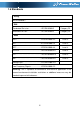
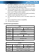
Wave form sinusoidal Load type PF 0.5~1, lagging THDV < 2% @ full linear load <5% @ full non linear load Overload In Line mode**: 10 min 1 min 10 s 100 ms In Battery mode: 2 min 30 s 100 ms 105~125% 125~150% >150% >170% 105~125% 125~150% >150% *The load capacity would be derated to 90% automatically when the output voltage is adjusted to 208VAC. **The overload capacity would be derated automatically in Line mode while the circumstance temperature is larger than 35 degree. BATTERIES Model No.
3.4 Typical Backup Time (Typical values at 25°C in minutes) Model No. 100 % Load PowerWalker VFI 6000T LCD PowerWalker VFI 10000T LCD 5 4 3.5 Dimensions and Weights Model No. PowerWalker VFI 6000T LCD PowerWalker VFI 6000T LCD L PowerWalker VFI 10000T LCD PowerWalker VFI 10000T LCD L Dimensions W×H×D (mm) Net Weight (kg) 260 x 708 x 550 80 260 x 708 x 550 25.5 260 x 708 x 550 84 260 x 708 x 550 29.
USB Port RS 232(optional) EPO Port Dry contact Intelligent Slot Parallel Port Fan Maintenance Switch Input Breaker Terminal Block PowerWalker VFI 6000T LCD (L) PowerWalker VFI 10000T LCD (L) Fig.
4. Installation The system may be installed and wired only by qualified electricians in accordance with applicable safety regulations! When installing the electrical wiring, please note the nominal amperage of your incoming feeder. 4.1 Moving to The Installation Site The series UPS has wheels making it easy to move the UPS to the installation site after it has been unpacked.
2. Check all packaging materials to ensure that no items are missing. The shipping package contains: ● A UPS ● A user manual ● A USB cable ● A RS232 cable (optional) ● A parallel port cover plate ●Terminal splices 12pcs (using for the wire connection on input terminal) ● EPO connector 3. Inspect the appearance of the UPS to see if there is any damage during transportation. Do not turn on the unit and notify the carrier and dealer immediately if there is any damage or lacking of some parts. 4.
4.3.
Fig.4-6 Typical external isolating device installation 2) No matter the UPS is connected to the mains power or not, the output of the UPS may be electrically live. The parts inside the unit may still have hazardous voltage after turning off the UPS. To make the UPS have no output, power off the UPS, and then cut off the mains power supply, wait the UPS shut down completely. 3) Open the terminal block cover located on the rear panel of UPS, please refer to the appearance diagram.
8) Connect other input and output wires to the corresponding input and output terminals according to the following diagram. 9) It is requested to use the accessorial terminal splices which can be compacted on the wires tightly, to ensure the connection between the wires and the terminal block is reliable. Fig. 4-7 Input and output Terminal Block wiring diagram Notes: 1) If the UPS is used in single mode, JP1 and JP2 must be connected.
14) If it is necessary to connect the inductance load such as a monitor or a laser printer to the UPS, the start-up power should be used for calculating the capacity of the UPS, as its start-up power consumption is too big to make the UPS which capacity is small fail easily. 4.4 Operating Procedure For Connecting with The External Battery (Only for “S” model) 1. The nominal DC voltage of external battery pack is 240VDC. Each battery pack consists of 20 pieces of 12V maintenance free batteries in series.
3) Set the external battery pack breaker in “OFF” position and connect the 20 pieces of batteries in series. 4) Connect the external battery pack to the battery terminals. Check the polarity of connection is correct. 5) Set the breaker of the battery pack in the “ON” position. 6) Set the mains input breaker in the “ON” position, the UPS would power on and start to charge the battery pack. 4.5 EPO Connection 4.5.
5. Operation 5.1 Display Panel The UPS has a four-button dot matrix LCD with dual color backlight. Standard back-light is used to light up the display with white text and a blue background. When the UPS has a critical alarm, the backlight changes the text to dark amber and the background to amber. Besides the LCD, the UPS has four colorized LEDs to provide more convenient information. Fig.
Enter main menu When displaying default UPS status summary screen, press this button for >1s to enter the main menu tree Exit main menu Press this button for >1s to exit the present menu to default system status display menu without executing a command or changing a setting Scroll up Press this button for >100ms&<1s to scroll up the menu option Scroll down Press this button for >100ms&<1s to scroll down the menu option Enter next menu tree Press this button for >100ms&<1s to select the present menu
Note: : ●: Lightened constantly : #1-#4 Lightened circularly : Flashing ↑: Depended on the fault/warning status or other status Table 5-3 Alarm definition UPS condition Buzzer status Fault active Warning active Continuous Beep every second Beep every 4 seconds, if battery low, buzzer Beep every second Beep every 2 minutes Beep twice every second Battery output Bypass output Overload The UPS provides useful information about UPS itself, load status, events, measurements, identification, and settin
UPS operating status Battery information Input 220 V Output 273.0 V 60 Hz 220 V UPS output information 60 Hz 100% 5400 W Utility input information Load information Fig. 5-2 The default LCD display The more detailed operation of LCD is illustrated in the chapter of 5.4. 5.2 Operating Mode The different graphic symbol could be displayed corresponding to current operating mode or status. 5.2.1 Line mode The example of LCD display in Line mode is shown in the following diagram. Fig.
5.2.2 Battery mode The example of LCD display in battery mode is shown in the following diagram. Fig. 5-4 Battery mode When the UPS is running in battery mode, the buzzer beeps once every 4 seconds. 5.2.3 Bypass with output The LCD display in bypass mode with output is shown in the following diagram. The UPS does not have the backup function when it is in bypass mode. The power used by the load is supplied from the mains power via internal filter. The UPS will beep once every 2 minutes in bypass mode.
5.2.4 Bypass without output The LCD display in bypass mode without output is shown in the following diagram. Fig. 5-6 Bypass mode without output 5.2.5 HE mode (High Efficiency mode) It is also called economy mode. After the UPS is turned on, the power used by the load is supplied from the mains power via internal filter while the mains power is in normal range, so the high efficiency could be gained in the HE mode.
2) It is attention that the transfer time of UPS output from HE mode to battery mode is about 10ms. But it is still too long for some sensitive load. 5.2.6 Converter mode In converter mode, the UPS would free run with fixed output frequency (50Hz or 60Hz). Once the mains power is loss or abnormal, the UPS would transfer to battery mode and the load is supplied continuously. Fig. 5-8 Converter mode 1) 2) The function could be enabled through the LCD setting or the software (Winpower, etc.).
Fig. 5-9 Warning 5.2.8 Fault When the fault occurs, it illustrates that some fatal problems happened, the UPS would directly cut off the output or transfer to bypass, and keep alarming. The backlight of LCD would also turn to red. The detailed fault table is shown in chapter of 7. Fig. 5-10 Fault 5.2.9 Other status When the UPS is overload, the alarm will beep twice every second.
Fig. 5-11 Overload While doing the battery test, LEDs would be lighted circularly, and the symbol of battery test would be shown on the display. Fig. 5-12 Battery test And if the battery status detected is “battery disconnected”, the symbol of battery failure would be shown and UPS would alarm. Fig.
5.3 Turning On and Turning Off UPS Attention: The UPS could only be turning on while connecting with the mains at the first time. Attention: Please switch off the connected loads first before turning on the UPS, and switch on the loads one by one after the UPS is turned on. Switch off all of the connected loads before turning off the UPS. 5.3.1 Turning on UPS with mains 1) Check all the connection is correct. Check the breaker of external battery pack is in “ON” position.
5.3.3 Turning off UPS with mains 1) 2) To turn off the inverter of UPS by pressing button continuously for more than 3s and the buzzer will beep for 3s. The UPS will turn into Bypass mode at once. When completing the above action, UPS output voltage is still present. In order to cut off the UPS output, simply cut off the mains power supply. A few seconds later, LCD display shuts down and no output voltage is available from the UPS output terminal. 5.3.
WELCOME UPS status Alarm # 41 Event log Battery Volt: 220V Battery charging Charger level:100% Measurements Status: Increase mode Para Num: 2 Running time: 0001:03: 01: 00 Control Identification Settings Fig.
5.4.2 The UPS status menu By pressing on the menu of “UPS status”, the display would enter the next UPS status menu tree. The content of UPS status menu tree is same as the default UPS status summary menu. By pressing tree. >1s, the display would return the last main menu Fig.
5.4.3 The event log menu By pressing on the menu of “Event log”, the display would enter the next event menu tree. All the old event, alarm and fault have been recorded here. The information includes the illustration, the event code, and the operating time of UPS when the event happened. By press or <1s, all the event could be displayed one by one. The max number of record is 50, when the number is larger than 50, the oldest one would be changed to the newest information.
5.4.4 The measurement menu By pressing on the menu of “Measurement”, the display would enter the next measurement menu tree. A lot of detailed useful information could be checked here, Ex. the output voltage and frequency, the output current, the load capacity, the input voltage and frequency, etc. By pressing >1s, the display would return the last main menu tree. Fig.
5.4.5 The control menu By pressing on the menu of “Control”, the display would enter the next control menu tree. 1) Single UPS turn off: is one command to turn off one UPS which is operated currently in a parallel system, and other UPSs continue working to supply the load in the parallel system. 2) Single UPS battery test: is one command to control one UPS which is operated currently in a parallel system to do the battery test singly, and other UPSs do not do the battery test.
Fig.
Example: clear EPO status Clear EPO status By press <1s Status:EPO active Clear:no By press or <1s Status:EPO active Clear:yes By press >1s Status:EPO inactive Clear:no Note: First make sure the EPO signal is inactive or the LCD will show below information and the EPO active status couldn’t be cleared. Fig. 5-19 clear EPO status 5.4.6 The identification menu on the menu of “Identification”, the display would enter By press the next identification menu tree.
Fig. 5-20 Identification menu tree 5.4.7 The setting menu Please contact your local distributor for further information before using the settings. Some settings would change the specification, and some settings would enable or disable some functions. The unsuitable option set by user may result in potential failures or protecting function loss, even directly damage the load, battery or UPS. The most of settings could only be done while UPS is in Bypass mode.
Fig. 5-21 Setting menu tree on the menu of “Identification”, the display would enter the By press next setting menu tree if “User password” is disabled. If “User password” is enabled, the user should enter the password by press , , and , then enter the next setting menu tree.
Table 5-4 Submenu item Optional Values Default value User password enabled/disabled disabled Audio alarm enabled/disabled enabled Rated output voltage 208/220/230/240V 230V Output frequency autosensing/50/60Hz autosensing Power strategy** normal/high efficiency/ converter normal DC start enabled/disabled enabled Site wiring fault alarm Ambient temperature warning Automatic battery tests period Auto Restart enabled/disabled enabled enabled/disabled enabled 0-31days 7days enabled/d
Example: set rated output voltage value Fig.
6. Special Function The series UPS has some special functions, which could satisfy some special application of user. And the functions have own features, please contact your local distributor for further information before using the function. 6.1 HE Function 6.1.
6.2 Converter Function 6.2.1 Brief introduction of Converter function In converter mode, the UPS would free run with fixed output frequency (50Hz or 60Hz). Once the mains power is loss or abnormal, the UPS would transfer to Battery mode and the load is supplied continuously. The great virtue is the output frequency is fixed, which is required by some very sensitive loads. But the disadvantage is the load capacity of UPS should be derated to 60% in converter mode. 6.2.
6.3.2 Parallel installation and operation How to install a new parallel UPS system: 1) Before installing a new parallel UPS system, user need to prepare the input and output wires, the output breaker, and the parallel cable. 2) Users need to use a standard 25-pin communication cable, which should have 25 cores, corresponding stitches and shield, as the UPS parallel cable. The length of the parallel cable is appropriate to be less than 3m.
IP_G IP_N IP_L B+ B- B_G J1 BAT PACK #1 (For “ S” model) IP_G IP_N IP_L B+ B- B_G J1 OP_G J2 OP_N OP_L OP_G UPS#2 O/P Breaker Main I/P Breaker I/P Ground BAT Ground BAT PACK #2 (For “ S” model) OP_N OP_L UPS#1 O/P Breaker BAT Ground J2 O/P Ground Main O/P Breaker TO UTILITY TO LOAD Fig.
Fig. 6-2 Parallel System Installation Diagram 10) Do not switch on the output breaker of each UPS, switch on the input breaker of the each UPS, the UPS should work in bypass with output, observe their display to check if there are any warning or fault information, measure the output voltage of each UPS separately to check if the voltage difference between them is less than 1V. If the difference is more than 1V, check the wiring.
13) Press the button of one UPS, each UPS would start to turn on, after turning on, the UPSs should work parallel in the Line mode. How to join a new UPS to a parallel system: 1) First the parallel system must be installed one main maintenance mechanical switch or static switch. 2) Regulate the output voltage of the new UPS separately: check if the output voltage difference between the new UPS and the parallel system is less than 0.5V.
3) 4) 5) 6) automatically, set the own maintenance switch of each UPS from “UPS” to “BPS”. Set the main maintenance switch or static switch from “UPS” to “BPS”, switch off the main output breaker and the main input breaker, and the UPSs would shut down. Ensure the UPSs shut down totally, remove the wanted UPS and reinstall the new UPS parallel system by following step 1) to 9) of last chapter - “install a new parallel UPS system”.
7. Trouble Shooting If the UPS system does not operate correctly, first check the operating information on the LCD display. Please attempt to solve the problem using the table below. If the problem still persists, consult your dealer. 7.1 Trouble Shooting According To Warning Indication Problem Displayed Read EEPROM Error Epo Active Possible cause Remedy UPS internal fault EPO connector is closed Maintain bypass switch is open Consult dealer.
Over Charge Battery is over charged The UPS will turn off the charger until the battery voltage is normal Model Pin Error Ambient Over Temperature UPS internal fault The ambient temperature is too high Consult dealer. Check the environment ventilation. Heatsink Over Temperature Ambient NTC abnormal Inside temperature of UPS is too high UPS internal fault Check the ventilation of UPS and the ambient temperature. Consult dealer.
7.2 Trouble Shooting According To Fault Indication Problem Displayed Inv Overload Fault Possible cause Remedy Check the loads and remove some non-critical loads. Overload Check if some loads are failed. Byp Overload Fault Check the loads and remove some non-critical loads. Overload Check if some loads are failed. Output Short Circuit Output short circuit Remove all the loads. Turn off the UPS. Check if UPS output and loads is short circuit. Ensure short circuit is removed before turning on again.
7.3 Trouble Shooting In Else Cases Problem Possible cause Remedy No indication, no warning tone even though system is connected to mains power supply No input voltage BYPASS LED light up even though the power supply is available Inverter not switched on Press On-Switch “I” to turn on UPS. BATTERY LED lights up, and audible alarm sounding every 1 beep in every 4 seconds Input voltage and/or frequency are out of tolerance Check input power source.
8. Battery Maintenance Battery replacement should be performed by qualified personnel. This series UPS only requires minimal maintenance. The battery used for standard models are value regulated sealed lead-acid maintenance free battery. These models require minimal repairs. The only requirement is to charge the UPS regularly in order to maximize the expected life of the battery.
9. Communication Port 9.1 USB Interface The USB port is compliance with USB 1.1 protocol for its communication software. 9.2 Dry contact Interface This series UPS has independent dry contact interface. Please contact your local distributor for details. The following is the pin assignment and description of DB-9 connector.
RS-232 communication port pin assignments Pin 1 2 3 4 5 6 7 8 9 Signal name Tx Rx GND Function Unused Transmit to external device Receive from external device Unused Signal common Unused Unused Unused Unused Direction from the UPS Not applicable Out In Not applicable Not applicable Not applicable Not applicable Not applicable Not applicable 9.4 Intelligent slot This series is equipped with an intelligent slot for other optional card to achieve remote management of the UPS through internet / intranet.
10. Software Installation WinPower is UPS monitoring software, featuring user-friendly interface to monitor and control your UPS. This unique software provides complete power protection for computer system while power failure. With the software users can monitor any UPS status on the same LAN.
55