PowerWalker VFI 3/3 Series VFI 20000TP~40000TP 3/3 BX 380/400/415V 50/60Hz (3-phase input/output) User Guide
EN ©2013 BlueWalker GmbH All Rights Reserved The contents of this manual are the copyright of the publisher and may not be reproduced (even extracts) unless permission granted. Every care has been taken to ensure the accuracy of the information contained in this manual, but no liability can be accepted for any errors or omission. The right to make design modifications is reserved.
Safety Instructions Operation Safety 1.Prior to the application, please read “Safety Instructions” carefully to ensure correct and safe application. Please keep the user manual properly. 2.During operation, attention should be paid to all warning symbols and operations should be followed strictly as required. 3.Equipment is not supposed to be used in environment that directly exposed to the sunlight or raindrops or in humid. 4.
3.Replacement of accumulator batteries requires a match of same type and model with equal quantity. 4.As accumulator batteries may contain potential electric shock and short-circuit current danger, to avoid accidents that might be thus resulted, the following warnings should be observed during battery replacement: A.Do not wear watches, rings or similar metallic items; B.Use insulated tools; C.Put on rubber shoes and gloves; D.Do not place metallic tools or similar metallic parts on the batteries; E.
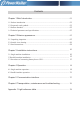
Contents 01 Chapter 1 Brief introduction--------------------------------------1.1 Product introduction-------------------------------------------------- 01 1.2 Frequently used symbols---------------------------------------------- 01 02 1.3 Product standard------------------------------------------------------1.4 Technical parameters and specifications------------------------------------03 Chapter 2 Exterior appearance-----------------------------------05 05 2.
Chapter 1 Brief introduction 1.1 Product introduction PowerWalker VFI 3/3 Series products are high-efficiency and high-performance, doubleconversion three phase input and three phase output UPS, unit capacity ranging between 20KVA-40KVA. Categorized by capacity, the products can be further divided into 20KVA, 30KVA and 40KVA.
Remark: Proper attention should be given to all warning symbols on the equipment and no tearing or damaging of these symbols is allowed. 1.
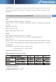
WARNING:This is a product for commercial and industrial application in the second environment-installation restricitions or additional measures may be needed to prevent disturbances EN 1.4 Technical parameters and specifications Input Wire connection: three phase four wire +grounded Voltage: 380 ×(1 +25% / -45%)VAC (when input voltage<75%, output power derating is required) Frequency: 40Hz-70Hz Power factor: over 0.
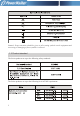
Altitude: below 1000m Storage temperature: -25℃~ +55℃ Remark: when UPS has been stored under a temperature of 0℃ or has been inactive for a long time, it is suggested that prior to start-up of UPS environmental temperature should be brought back to 0℃ or above for 2 hours. General specifications VFI 20000TP 3/3 BX Machine size(mm) L*W*H 643*420*956 VFI 30000TP 3/3 BX 710*470*1150 110 160 VFI 40000TP 3/3 BX 710*470*1150 114 164 MODEL NO 4 N.W(kg) G.
Chapter 2 Exterior appearance 2.1 Unpacking inspection EN 1.Unpack and there should be: Winpower disc User Manual 2. Check whether UPS is damaged during the process of transportation or not. Should any damage be observed or parts be found missing, do not start the machine. Forwarder and distributor should be immediately advised. Remark: prior to transportation make sure of the height of the door and other obstacles standing in the passage.
2.2 Exterior figure Exterior figure of VFI 20000TP 3/3 BX UPS EXT.
CHGR FAN EN Maintenance switch Main Ⅱ(Optional kit) Main Ⅰ Front view (without front panel) Exterior figure of VFI 30000TP 3/3 BX,VFI 40000TP 3/3 BX UPS LCD panel EXT.
CHGR FAN Maintenance switch Main Ⅱ(Optional kit) Main Ⅰ Front view (without front panel) 2.3 Panel instructions ① AC: this light and inverter light will turn “green” when UPS is powered directly by AC; ② Inverter: this light will turn “green” when UPS is loaded through the inverter; ③ Battery: this light will turn “yellow” when UPS is powered by batteries; ④ Bypass: this light will turn “green” when UPS is power loaded by AC through bypass.
⑤ Fault: this light will turn and stay “red” with continuous warning tone being given off in case of UPS abnormal function; or flash “red” with intermittent warning tone being given off. ⑥ LCD: display UPS condition. ⑦ :Confirm/Enter; press this button to select a menu or confirm an operation. ⑧ :PageDown; press this button to switch to next screen display under the same menu. ⑨▲ :PageUp; press this button to return to next screen display under the same menu.
Chapter 3 Installation instructions 3.1 Single machine installation 1) The installation of this unit must be performed in compliance with the electrical code by professional personnel. 2) Install the UPS in a clean and stable environment that is free of vibration, dust, high humidity, flammable gas, flammable liquid or caustic substance. 3) To ensure normal UPS performance, ambient temperature should range between 0℃ 40℃ .
for each group being168VDC-192VDC. Battery capacity and number of group can be selected at your option. Battery pack must be equipped with DC switch (it is suggested that selection of DC switch should be in line with installation drawing for wire connection). 8) Brake pad: use wrench 19# in clockwise direction so as to screw the brake pad down to the ground, keeping the machine from moving.
Remark: 1. For the Series UPS, input neural line should be directly connected to input “N” terminal of UPS wire connection terminal bay without AC input idle-run; 2. When single-phase current exceeds 100A, switches of protective atmosphere should be equipped with arc control devices; 3. Battery positive/negative wire size: indicates UPS and battery box wire size; red wire signifies the positive polarity and black wire the negative,while blue wire the neutral. 4.
EN 3.3 Procedures of connecting battery box to UPS 1. Make sure that UPS input and output terminals are uncharged; 2. Turn off the battery switch on battery box; 3. Connect “+”, “N” and “-“ of battery to the corresponding terminal bay of UPS; 4. Use multimeter (DC Voltage) to measure the voltage of positive and negative batteries as well as positive and negative polarity.
Chapter 4 Operation 4.1 Single machine operation 1. Make sure A, B and C phase sequences are correctly connected and then supply power to UPS. 2. Turn on the switch on battery box (make sure that the “+”, “N” and “-” of terminal bay are in accordance with those on the battery box). 3. Switch on “input breaker” (Line input breaker: Main Ⅰ ; bypass input breaker: Main Ⅱ (if assembled)) on UPS and fans start to rotate for UPS self-inspection.
EN 5)Press ▼ again to obtain the below information 7)Press ▼ again to obtain the below information 6)Press ▼ again to obtain the below information 8)Press ▼ again to obtain the below information VFI 20000TP 3/3 15
Remark: when malfunction occurs, “x” will appear at the lower right corner of the picture while when warning occurs “ ” will appear at the same position (as illustrated in the below picture with battery mode as an example). 4.
5)Battery power supply (switch off line input breaker) EN 5.
LOAD LOAD 5)Select “Yes, Confirm” to switch off the machine 6)Normal Switch-off LOAD Remark: If you intend to switch off only one set of UPS among the parallel machine system, select “single machine switch-off”; if switch-off is intended for the entire parallel machine system, select “parallel machine switch-off”. 6.
EN 7. Setting action (press ESC to exit the above picture) You are able to access Setting picture by using user combination (default: 1234, subject to personal modification) so as to set the following programs.
3)Input Password display 4)Input password and press ENTER 8. The Series is capable of DC start-up without AC input, panel display being similar to switch-on picture with AC supply. DC switch-on and off are available by following instructions appearing in the pictures. 9.
4.2 Parallel machine operation 1. Redundancy introduction N+X is currently the most reliable power supply structure, in which N indicates the minimum UPS number required for the total load and X is the redundant UPS number, namely, the malfunctioning UPS number that the system can simultaneously bear. The larger X is, the higher reliability of system will be. For instance, if the total load of a customer registers 55kVA, we can use VFI 20000TP 3/3 BX for N+X design.
3. Operation instructions 1)Follow single machine operation instructions for general operation. 2)After switch to Line mode, all machines will jump to conversion mode; switch off: when switch-off is conducted under conversion mode, all machines will simultaneously switch off inverter and then convert to the bypass mode after the last machine completes switch-off action.
Chapter 5 Communication Interface The Series provide Intelligent Slot, Expanded Slot, PARALLEL, EXT.BATTERY TEMP PROBE, AS400, EPO, RS485 and RS232 as well as SERVICE Supervising Communication Interface exclusively available to PowerWalker technical personnel. 1 3 PARALLEL PARALLEL EXT.BATTERY TEMP PROBE 5 6 AS400 EPO 8 RS485 Intelligent slot SERVICE RS232 Expanded slot 2 4 7 9 1.
RS232 port: RS485 port: 24
AS400 port: EN 25
Chapter 6 Transportation, Maintenance and Troubleshooting Remove UPS Make preparation for UPS relocation according to the following steps. Remark: special equipment (forklift) is needed for loading and unloading due to the heavy weight of UPS. 1. Switch off all equipments connected to UPS. 2. Turn off UPS AC switch and battery pack switch. 3. Disconnect all wires from UPS terminal bay. 4. Put UPS back into the original carton for relocation. Maintenance The Series UPS requires minimum maintenance. 1.
Troubleshooting Should maintenance prove necessary, the following steps should be followed: 1. Check if UPS input wiring is done properly. 2. Check if all air switches are tripped out. 3. Check if voltage input is within specified range. EN Please refer to “Light Reference Table” of this User Manual first and then conduct proper treatment. If problems still exist, please record UPS model, serial number as well as purchase date, symptom on fault, light condition, LCD malfunction or warning information.
Appendix 1 Light Reference Table Should any display or warning message excluded in the above table be found, please contact distributor.
614-01720-00