POWERTEC Industrial Motors DFS-1 SOFTWARE RELEASE 1.0 MICROPROCESSOR BASED BRUSHLESS D.C.
A subsidiary of POWERTEC Industrial Corporation Mailing Address: P.O.
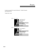
ERRATA Corrections to page 44 of the manual, Attachment A: Detailed Commands Read Speed/Status (81) Changes shown in gray [ST2] - 7 6 5 4 3 2 1 0 [ST1] - 7 6 5 4 3 2 1 0 DFS-01IM PM94290 Local/Remote (0,1) Master/slave (0,1) At Speed (1) Fwd. Dir.
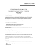
Additional Info DFS Software Modification For Dynamic Braking or Output Contactor Operation 25 October, 1994 Functional Description A new function for Contactor Aux has been added to the digital input choices. When configured as described in the example, 24VDC must be present at this input for the drive to run. Parameter #62, Contactor Delay, is a number of 25ms intervals that will occur between the DFS controller acceptance of a run command and the firing of the transistors.
1.0 INSTALLATION The DFS-1 printed circuit board mounts on any POWERTEC Brushless DC motor control except the Model 500. The Model 1000 is used here for illustration purposes only. 1.
CONTENTS Introduction ............................................................................................................................... 1 Summary of Warranty and Disclaimer ...................................................................................... 2 WARNING! ............................................................................................................................... 2 1.0 Connections .................................................................................
23. 24. 25. 26. 27. 28. 29. 30. 31. 32. 33. 34. 35. 36. 37. 38. 39. 40. 41. 42. 43. 44. 45. 46. 47. 48. 49. 50. 51. 52. 53. 54. 55. 56. 57. 58. 59. 60. 61. ANALOG INPUT #2 LOW ENGINEERING UNITS (EGU) .............................................................. 22 ANALOG INPUT #2 HIGH ENGINEERING UNITS (EGU) ............................................................. 22 ANALOG OUTPUT #1 MODE SELECT .............................................................................................
5.0 DFS-1 ERROR CODES .................................................................................................. 39 6.0 COMMUNICATION PROTOCOL .................................................................................. 41 COMMAND LIST ........................................................................................................................................ 42 PARAMETER LIST ..........................................................................................................
THIS PAGE WAS INTENTIONALLY LEFT BLANK. Page 4 DFS-1 Manual Revised 7/95 POWERTEC Ind. Corp.
INTRODUCTION A s the computer revolution takes greater control of industrial processes, there is a growing need for more intimate control of the process parameters. It is becoming ever more necessary to control the important characteristics of motors directly from computers and microprocessorbased controllers. Such control cannot wait for operator intervention when changes occur in milliseconds and tolerances are measured in thousandths.
SUMMARY OF WARRANTY AND DISCLAIMER POWERTEC Industrial Corporation warrants the DFS-1 to be free from defects in materials and workmanship for a period of one year from the date of shipment from the factory, or if purchased from an authorized POWERTEC distributor or Original Equipment Manufacturer, not more than 18 months from the date of shipment from the factory.
1.0 CONNECTIONS POWER CONNECTIONS: POWERTEC Brushless DC motor controllers are supplied with nominal input voltages of 230, 380, and 460VAC. Three phase input power is required. The input is not phase sensitive. Connect the appropriate power supply to the input fuses at L1, L2, and L3 (check nameplate for proper input voltage and capacity). Connect the output terminals T1, T2, and T3 to the respective terminals on the Brushless DC motor.
There are two analog input ports to the DFS-1 on TB1:B. When used as a voltage input, both of the analog inputs are a differential type of input with a minimum input impedance of 200 Kohms. When using one of the analog inputs for a voltage input, the input common at terminal 1 on TB1:B should be used for shields.
4. Comm set (value is set via Communications) 5. Commanded speed Analog Output #1 default is a -10 to +10VDC signal representing motor speed. The outputs are on TB1:B terminals 8 (+) and 10 (-). The opposite polarity is available by a parameter change. See the description for parameters #26 and #27. The default for Analog Output #2, terminals 9 (+) and 10 (-), is -10 to +10VDC representing motor load, 0% to 150% load. The opposite polarity is available by changing a parameter.
FREQUENCY OUTPUT: DIGITAL INPUTS: There are two outputs available to supply a frequency for external use. The first is located at TB2:B terminal 10 (+) and 11 (-). This is an output which is intended to provide a reference frequency input for another DFS-1, BCDMAX or CRM-1. This output is not compatible with the DIGIMAX. It will provide a signal of +/1.5V minimum when connected to another DFS-1's reference frequency input.
The programmable inputs (TB2-A4 through TB2-A10) may be programmed for jog, thread, or other preset speeds. The inputs may also be used to change torque levels, trim values, or ramp rates. Any value which can be affected by a parameter can be changed by a digital input. DIGITAL OUTPUTS: Digital outputs are located on TB2:B. The four outputs are normally open relay contacts. The contacts are rated at 120VAC at 1 amp, resistive.
THIS PAGE WAS INTENTIONALLY LEFT BLANK. Page 12 DFS-1 Manual Revised 7/95 POWERTEC Ind. Corp.
DEFAULT SETUP The concept behind the DFS-1 calls for fully programmable inputs and outputs. The ability to change analog and digital inputs and outputs at will lends a whole new meaning to the word "flexibility". POWERTEC has established a set of "default" parameters which will leave the setup of the DFS-1 in a way that will operate a motor in the basic configuration (see figure 3 on page 3 and figure 4 on page 4). There are two good reasons for doing this: 1.
THIS PAGE WAS INTENTIONALLY LEFT BLANK. Page 14 DFS-1 Manual Revised 7/95 POWERTEC Ind. Corp.
2.0 SPECIFICATIONS 5.0 POWER SUPPLIES +24VDC • Available at TB2:A14, and TB2:B1. • The combination is fused at 250 milliamps (mA). The fuse is self-healing. • The opening of the fuse alerts the microprocessor. • These supplies should only be used for push-buttons, relays, PLC outputs, etc. which interface directly with the DFS-1. They should not be used as general purpose supplies. +10VDC • Reference supply available at TB1:B2. This output is rated at 100mA.
FREQUENCY INPUTS AND OUTPUTS DIGITAL INPUTS There is one frequency input and there are two frequency outputs available. INPUT #1 REFERENCE FREQUENCY INPUT TB2:A Terminals 11 (+) and 12 (-). • This is a line receiver type input which must be driven by a differential line driver output. • This frequency input requires a frequency 16 times the feedback from the motor. • The feedback from the motor is normally 120 PPR for 4 pole motors and 240 PPR for 8 pole motors.
COMMUNICATIONS Standard: RS-485 Data Rates: 300, 600, 1200, 2400, 4800, 9600, 19.2K, and 38.4K baud Addresses: 1 to 255 Protocols: POWERTEC Binary protocol Distance: 4000 meters (about 12,000 feet) maximum with twisted pair shielded cable Nodes: 32 maximum Revised 7/95 POWERTEC Ind. Corp.
THIS PAGE WAS INTENTIONALLY LEFT BLANK. Page 18 DFS-1 Manual Revised 7/95 POWERTEC Ind. Corp.
3.0 DFS-1 PARAMETERS DFS-1 parameters are stored as DOUBLE WORD values (32 bits), regardless of the actual size of the data. This method is used to simplify the entire system at a cost of a little extra data storage. A double word consists of four BYTES (8 bits). Each byte is a hexadecimal (base 16) value which ranges from 00h (0 decimal) to FFh (255 decimal). The largest number used in the DFS-1 parameters is 99,999 decimal, which, in hexadecimal notation is 0001 869Fh.
0001b) , the Run FUNCTION cannot be controlled from the terminal strip, but can only be controlled through the external communications link or the local comm link (keypad display unit). If VL1 has a value of 73 (0111 0011b), all functions except UP and DOWN are controlled remotely. NOTE: Parameter #3 ONLY determines whether a FUNCTION is controlled locally or remotely. This parameter has nothing to do with the assignment of functions to terminals.
0000h Normal current limits (motor current not limited at a lower level) 0001h Motoring torque setpoint (motoring current to be limited at a lower level) 0002h Regenerative torque setpoint (regenerative current to be limited at a lower level) 0003h Horsepower setpoint (the product of motor current and motor speed is limited) 0004h through 000Fh available for future use When in the normal mode, the current in the motor is not controlled below current limit.
8. MASTER RAMP UP TIME 10. SLAVE RAMP UP TIME USE PARAMETER #8 TO SET THE TIME TO RAMP FROM ZERO TO FULL SPEED. RANGE OF VALUES: 0000 0001h to 0003 E418h 1 TO 255,000 (decimal) Default Value: 0000 2710h 10,000 (decimal) USE PARAMETER #10 TO SET THE UP RAMP TIME WHEN THE RATIO IS CHANGED. RANGE OF VALUES: 0000 0001h to 0003 E418h 1 TO 255,000 (decimal) Default Value: 0000 2710h 10,000 (decimal) This is the acceleration time from zero speed to full speed in the MASTER mode.
12. MASTER PRESET SPEED USE PARAMETER #12 TO SET A PRESET SPEED WHICH CAN BE TOGGLED IN AND OUT. RANGE OF VALUES: 0000 0000h to 0000 2710h 0 TO 10,000 (decimal) Default Value: 0000 00C8h 100 (decimal) The MASTER preset speed is the speed to which the motor will go when a PRESET input is activated on one of the Digital inputs (any of the seven digital inputs may be programmed as a PRESET input) when the DFS-1 is in the MASTER mode.
the slave unit to match the line speed, motor speed, or section (master). Many times, however, the gearing between the slave motor and the surface of a roll is not the same as the master, or the diameter of the rolls vary from section to section, or motors of different RPM’s may have to be tracked. The BASE RATIO is a correction factor which allows the SETPOINT to be adjusted.
As a Speed Reference input ( ...01h), Analog input #1 sets the speed of the controlled motor directly if the DFS-1 is set up in Master Mode (parameter #5 - VL2 VL1). If the DFS-1 is in SLAVE mode, Analog Input #1, when set to ...01h will act as a Ratio SETPOINT. The External Torque Limits are used to set limits on the motor current which are below the current limit level. When parameter #5 VL4 VL3 is set to 00 01h, or 00 02h, Analog Input #1 may be set to ...03h or ...
20. ANALOG INPUT #1 HIGH ENGINEERING UNITS (EGU) USE PARAMETER #18 TO SELECT THE MAXIMUM ANALOG INPUT #1 EFFECT. RANGE OF VALUES: FFFE 7961h to 0001 869Fh -99,999 to +99,999 (dec.) Default Value: 0000 06D6h 1750 (decimal) (See Parameter 14 for the definition and purpose of EGU) Parameter #20 sets the maximum level for effectiveness of Analog Input #1 at the highest signal level. Assume that the maximum speed of the 1750 RPM motor is set to 12500 EGU’s in parameter #14 (representing, perhaps, 125.
25. ANALOG OUTPUT #1 MODE SELECT USE PARAMETER #25 TO SELECT THE SOURCE OF A SIGNAL AT ANALOG OUTPUT #1. RANGE OF VALUES: 0000 0000h to 0000 0003h 0 to 4 (decimal) Default Value: 0000 0001h 1 (decimal) Analog Output #1 may be programmed for several modes of operation. The mode affects where the signal at Analog Output #1 comes from. The following modes are provided for: 0000 0000h Disabled. 0000 0001h Actual Speed - Represents the speed of the motor from 0 to parameter #14.
29. ANALOG OUTPUT #2 LOW ENGINEERING UNITS (EGU) 30. ANALOG OUTPUT #2 HIGH ENGINEERING UNITS (EGU) USE PARAMETER #29 TO SELECT THE THRESHOLD OF ANALOG OUTPUT #2 EFFECT. RANGE OF VALUES: FFFE 7961h to 0001 869Fh -99,999 to +99,998 (dec.) Default Value: 0000 0000h 0 (decimal) USE PARAMETER #30 TO SELECT THE MAXIMUM ANALOG OUTPUT #2 EFFECT. RANGE OF VALUES: FFFE 7961h to 0001 869Fh -99,999 to +99,998 (dec.
31. DIGITAL INPUT #1 FUNCTION 32. DIGITAL INPUT #2 FUNCTION USE PARAMETER #31 TO SELECT THE #1 DIGITAL INPUT FUNCTION. RANGE OF VALUES: 0000 0000h to 0001 000Fh no decimal significance Default Value: 0001 0001h no decimal significance USE PARAMETER #32 TO SELECT THE #2 DIGITAL INPUT FUNCTION. RANGE OF VALUES: 0000 0000h to 0001 000Fh no decimal significance Default Value: 0001 0002h no decimal significance VL4 and VL2 are always 00. VL1 determines function of the input.
. DIGITAL INPUT #5 FUNCTION 38. DIGITAL OUTPUT #1 FUNCTION USE PARAMETER #35 TO SELECT THE #5 DIGITAL INPUT FUNCTION. RANGE OF VALUES: 0000 0000h to 0001 000Fh no decimal significance Default Value: 0001 0005h no decimal significance USE PARAMETER #38 TO SELECT THE #1 DIGITAL OUTPUT FUNCTION. RANGE OF VALUES: 0000 0000h to 0001 000Fh no decimal significance Default Value: 0001 0004h no decimal significance The setting options are the same as parameter #31.
39. DIGITAL OUTPUT #2 FUNCTION which is the REMOTE output. When the DFS-1 is in the remote mode, the contact between the terminals closes (the contact closes because VL3 is set to 01h). USE PARAMETER #39 TO SELECT THE #2 DIGITAL OUTPUT FUNCTION. RANGE OF VALUES: 0000 0000h to 0001 000Fh no decimal significance Default Value: 0000 0001h no decimal significance The setting options are the same as parameter #38. The default, by factory setting, is 0000 0001h, which is the FAULT output.
limit the output DRIVE current to 150%. This parameter CANNOT OVERRIDE that limit, but this parameter may be set for an ultimate current limit on drives which are built with more capability than the motors they run. In this way, short term 300% current ratings can be obtained. 45. DRIVE REGENERATIVE CURRENT LIMIT USE PARAMETER #45 TO SET THE REGENERATIVE CURRENT LIMIT OF THE DRIVE.
When parameter #48 is set to 0000 0000h, the DFS-1 is in the JUMP mode. In MASTER mode (set by parameter #5), when the UP input function is activated, the speed will increase by the amount set in parameter #49. As long as the UP function is active, the speed change will be held. When the UP function is released the speed returns to the SETPOINT. The same action applies to the DOWN function, the speed change set by parameter #50.
53. INPUT DEBOUNCE VALUE 55. MINIMUM RATIO USE PARAMETER #53 TO SET THE LENGTH OF TIME AN INPUT MUST BE ACTIVE TO BE ACTED UPON. RANGE OF VALUES: 0000 0000h to 0000 00FFh 0 to 256 (decimal) Default Value: 0000 0001h 1 (decimal) USE PARAMETER #55 TO SET THE LENGTH OF TIME AN INPUT MUST BE ACTIVE TO BE ACTED UPON. RANGE OF VALUES: 0000 0000h to 0001 869Fh 0 to 99,999 (decimal) Default Value: 0000 0000h 0 (decimal) Parameter #53 is the length of time, in 10 milliseconds (1 millisecond =.
58. SLAVE JOG RATIO 61. USE PARAMETER #58 TO SET A JOG SPEED WHICH CAN BE TOGGLED IN AND OUT. RANGE OF VALUES: FFFE 7961h to 0001 869Fh -99,999 to 99,999 (decimal) Default Value: 0000 00C8h 100 (decimal) The SLAVE JOG Speed is the speed to which the motor will go when a JOG input is activated on one of the Digital inputs (any of the seven digital inputs may be programmed as a JOG input) when the DFS-1 is in the SLAVE mode.
THIS PAGE WAS INTENTIONALLY LEFT BLANK. Page 36 DFS-1 Manual Revised 7/95 POWERTEC Ind. Corp.
4.0 DFS - 1 SETUP Parameter No. Value Parameter No.
4.1 BASIC SETUP OF THE DFS-1 CONTROLLER 1. SET PARAMETER #6 FOR THE MAXIMUM SPEED OF THE MOTOR IN RPM. The base speed of the motor is listed on the nameplate of the motor. If the base speed of the motor is other than 1750, you must change parameter #6. For instance, if the base speed of your motor is 2500 RPM, enter 2500 into parameter #6. 2. SET PARAMETER #14 TO THE ENGINEERING UNITS VALUE FOR PARAMETER #6. This is a number which is set equal to the base speed of the motor.
4.2 1. 2. MASTER MODE SETUP SET PARAMETER #5 FOR THE MASTER MODE. Set the basic operation in this parameter to MASTER. This parameter also has options for current control (see page 16). Selecting MASTER into the parameter takes care of the normal MASTER mode operation case because the default is normal current limits. Other choices are torque limiting (either motoring or regenerative) and horsepower control. If one of these choices is made, it will be necessary to either: 1.
4.3 1. 2. SLAVE MODE SETUP SET PARAMETER #5 FOR THE SLAVE MODE. Set basic operation in this parameter to 1 for SLAVE mode. For INVERSE SLAVE mode enter 2. INVERSE SLAVE mode affects the way a setpoint is entered. This parameter also has options for current control (see page 16). Setting a 1 takes care of the normal SLAVE mode because the default is normal current limits. Other choices are torque limiting (either motoring or regenerative) and horsepower control. For these options see page 16. 6.
4.4 1. 2. 3. INPUTS AND OUTPUTS SETUP SET PARAMETERS #17, #18, #19, AND #20 TO SET UP ANALOG INPUT #1. If Analog Input #1 is to be used for speed reference, which is the default mode, and the reference is to be 0 to +10VDC, no action is necessary to change from the defaults. If the input is to be 4 to 20mA, then parameter #18 must be changed. Set up parameters #19 and #20 to conform with the speed range set up by parameter #14.
4.5 COMMUNICATIONS SETUP The local operator's panel operates at CPU level and does not require the setup of any communications parameters. The following setup is for an external communications link. Before connecting to the external communications link, the following parameters must be set properly. The other parameters may be set after the link is established.
5.0 DFS - 1 ERROR CODES ERROR CODES FOR ON-BOARD DISPLAY The DFS-1 has a single-digit alphanumeric display to show error codes when something is wrong. Following is a list of the meanings of the numbers in that display: 0 All conditions nominal 1 Undervoltage trip ................................................. Line voltage dropped below minimum level 2 Overvoltage trip of drive ...................................... Bus voltage exceeded safe limit 3 Undervoltage timer tripped .....................
THIS PAGE WAS INTENTIONALLY LEFT BLANK. Page 44 DFS-1 Manual Revised 7/95 POWERTEC Ind. Corp.
6.0 COMMUNICATIONS PROTOCOL GENERAL DEFINITIONS: [STX] - 02h - Start of data [ETX] - 03h - End of data [ACK] - 06h - Acknowledge [NAK] - 15h - Negative Acknowledge [DLE] - 10h - Data Link Escape [CMD] -xxh - Command to be executed [CSM] - xxh - Checksum, 2’s complement sum of the data between the [STX] and [ETX] characters GENERAL NOTES: 1. The use of brackets in this document means that there is a single byte of information contained within the brackets.
COMMAND LIST Following is a list of commands to the unit. Detailed descriptions of each command are shown in attachment A beginning on page 55. Cmd # Description: 81h 82h 83h 8Bh Description: (Read Digital Output) Commands the unit to send the status of a digital output. 8Ch Description: (Set Digital Output) Commands the unit to turn on or off a specific digital output. Description: (Status Request) Respond with the current operating status which includes commanded speed, actual speed, and status bits.
PARAMETER LIST: Following is a list of the parameters used in DFS-1. For a detailed description of each parameter see the list in attachment B beginning on page 57.
ATTACHMENT A: DETAILED COMMANDS Read Speed/Status (81) Command: Set Speed (82) Read Speed/Status Description: This command tells the unit to respond with it’s current commanded speed, actual speed, load value, & status.
Message: [DLE][STX][UID][CMD][DLE][ETX][CSM] Response: If no errors and unit i.d. does not equal 0 [DLE][STX][UID][ACK][DLE][ETX][CSM] If unit i.d. = 0 (global command) then no response at all but all DIGIMAXes will execute simultaneously. else [DLE][STX][UID][NAK][ERR][DLE][ETX][CSM] Definitions: [ERR] - Reported Error.
[ERR] - Reported error [80] - Unit not in remote mode [84] - Illegal channel number [86] - Illegal Command number Message: [DLE][STX][UID][CMD][PRM][VL4] [VL3][VL2][VL1][DLE][ETX][CSM] Response: If no errors [DLE][STX][UID][ACK][DLE][ETX][CSM] else [DLE][STX][UID][NAK][ERR][DLE][ETX][CSM] Definitions: [PRM] - Parameter number [VL4]..
Response: CMD = [89] UID = [01] - [FF] DTA = [01 ]or [02] depending on which analog output If no errors [DLE][STX][UID][ACK][VL4][VL3] [VL2][VL1][DLE][ETX][CSM] else [DLE][STX][UID][NAK][ERR][DLE][ETX][CSM] Message: [DLE][STX][UID][CMD][DTA][VL4] [VL3][VL2][VL1][DLE][ETX][CSM] Response: If no errors [DLE][STX][UID][ACK][DLE][ETX][CSM] else [DLE][STX][UID][NAK][ERR][DLE][ETX][CSM] Definitions: [DTA] - Analog output number 01 or 02 [VL4]..[VL1] - Analog value cast as sealed between low EGU and high EGU.
Definitions: [DIG] - Digital output number 01 to 04 [VL4] - Always 00 [VL3] - Always 00 [VL2] - Always 00 [VL1] - Status of output 00 = off 01 = on [ERR] - Reported error [80] - Unit not in remote mode [84] - Illegal channel number [86] - Illegal Command number Set Operational Mode (8D) Command: Description: This command tells the unit to turn on or off specific input control functions such as run, stop, etc.
Message: [DLE][STX][UID][CMD][00][00] [SMH][SML][DLE][ETX][CSM] If you wish to determine the status of the digital inputs you must use command 8A (Read Digital Input). Response: If no errors [DLE][STX][UID][ACK][DLE][ETX][CSM] else [DLE][STX][UID][NAK][ERR][DLE][ETX][CSM] Definitions: [ERR] - Reported Error [80] - Unit not in remote. Returned if this command is sent and remote mode is not allowed in parameter 3. [86] - Illegal Command number. [87] - Illegal input number. [88] - Illegal input value.
any other mode than horsepower. Examples: Application Mode (8F) Command: Application Mode Command Description: This command reads/sets the operating setpoint by communications rather than using an analog input for the setpoint when a special application mode is active (see parameter 5). The modes currently defined are shown below. It is possible in the future that additional application modes may be added.
Additional Info DFS SOFTWARE MODIFICATION FOR DYNAMIC BRAKING OR OUTPUT CONTACTOR OPERATION Functional Description A new function for Contactor Aux has been added to the digital input choices. When configured as described in the example, 24VDC must be present at this input for the drive to run. Parameter #62, Contactor Delay, is a number of 25ms intervals that will occur between the DFS controller acceptance of a run command and the firing of the transistors.
Page 56 DFS-1 Manual Revised 7/95 POWERTEC Ind. Corp.
Revised 7/95 POWERTEC Ind. Corp.
THIS PAGE WAS INTENTIONALLY LEFT BLANK. Page 58 DFS-1 Manual Revised 7/95 POWERTEC Ind. Corp.
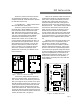
APPENDIX A RETROFITTING THE MODEL 1000, 1000A, OR 1000AR The DFS-1 Model 1000 series retro-fit kit consists of: Quantity 1 DFS-1 Printed Circuit Board with connector plugs Quantity 1 10 Pin Connector Cable Part # 3570-141420-001 Quantity 1 14 Pin Connector Cable Part # 3570-141419-001 Quantity 2 Nylon Spacer #6 x 1/4” diam x 1/4” long Quantity 2 Machine Screw, Pan-head, 6/32 x 1/2” long Quantity 4 Star Washer, #6 1.
THIS PAGE WAS INTENTIONALLY LEFT BLANK. Page 60 DFS-1 Manual Revised 7/95 POWERTEC Ind. Corp.
APPENDIX B MENU AND KEYPAD HIERARCHY When the DFS-1 is shipped, the factory presets the unit’s parameters according to the motor and drive’s specifications. The following pages describe the keypad’s hierarchal menus when the KDU-1 keypad and display unit has been installed and configured. At the opening menu level, the DFS-1’s status is displayed. The STATUS display shows the commanded speed, the load as a percent of Full Load Amps, and the actual motor speed.
Revised 7/95 POWERTEC Ind. Corp. C Figure 1.0 Status Select Menu Date Enter *Local/Remote Enter *Parameters History DFS-1 Manual Enb/Dsb Bklt Contrast Time Enter Fig. 2 Enter Fig. 30 Enter Enter Enter * Not visible in some modes.
THIS PAGE WAS INTENTIONALLY LEFT BLANK. Page 64 DFS-1 Manual Revised 7/95 POWERTEC Ind. Corp.
Revised 7/95 POWERTEC Ind. Corp. C Fig. 2 Fig. 3 Fig. 2 Fig. 1 SelectParameters Enter Select Communications Enter Fig. 3 Reset Parameters Enter Input/Output Slave DFS-1 Manual Master Drive Setup Fig. 4 Enter Fig. 5 Enter Fig. 6 Enter Fig. 7 Fig. 2 Select Communication Enter Select Unit ID Delay Enter Fig. 4 Protocol Baud Rate Select Analog In Enter Digital Out Enter Digital In Enter Remote Modes Enter Select Input/Output Enter Analog Out Fig. 8 Enter Fig. 9 Enter Fig.
THIS PAGE WAS INTENTIONALLY LEFT BLANK. Page 66 DFS-1 Manual Revised 7/95 POWERTEC Ind. Corp.
Revised 7/95 POWERTEC Ind. Corp. C Fig. 5 Fig. 2 Select Slave Fig. 6 Enter Select Preset Ratio 1 Enter Fig. 2 Select Master Fig. 7 Enter Select Preset Speed 1 Enter Fig. 2 Select Drive Setup Enter Select Mode Enter Fig. 24 Enter Set Point Control Enter Fig.
THIS PAGE WAS INTENTIONALLY LEFT BLANK. Page 68 DFS-1 Manual Revised 7/95 POWERTEC Ind. Corp.
Revised 7/95 POWERTEC Ind. Corp. C Fig. 9 Fig. 4 Select . Fig. 10 Fig. 4 Select Analog In Enter Select Channel # 1 Channel # 2 Enter Fig. 13 Enter Fig. 13 Fig. 12 Fig. 11 Fig. 4 Analog Out Enter Select Channel # 1 Channel # 2 Enter Fig. 16 Enter Fig. 16 Select . Digital In Fig. 4 Enter Select Channel # 1 Channel # 7 Channel # 6 Channel # 5 DFS-1 Manual Channel # 4 Channel # 3 Channel # 2 Enter Select . Digital Ou Select Channel # Fig. 18 Enter Fig. 18 Enter Fig.
THIS PAGE WAS INTENTIONALLY LEFT BLANK. Page 70 DFS-1 Manual Revised 7/95 POWERTEC Ind. Corp.
Revised 7/95 POWERTEC Ind. Corp. C Fig. 13 Fig. 14 Fig. 13 Select . AI Channel Fig. 9 Select # 1 or 2 Ente r Select Mode Calibration High EGU Low EGU Enter Fig. 14 Select General Purpose Enter Horsepower Enter Enter DFS-1 Manual Fig. 15 Fig. 16 Fig. 13 Select Enter Enter Modes 15 - 6 Enter Signal Condition Enter AI Mode Fig. 15 Enter Enter AI Sig.
THIS PAGE WAS INTENTIONALLY LEFT BLANK. Page 72 DFS-1 Manual Revised 7/95 POWERTEC Ind. Corp.
Revised 7/95 POWERTEC Ind. Corp. C Fig. 17 Fig. 16 Select Fig. 18 AO Mode Enter Select General Purpose Enter Modes 15 - 5 Enter Fig. 19 Fig. 11 Select DI Channel Fig. 18 Select # 1 or 2 Enter Select Mode Polarity Enter Fig. 19 Enter Fig. 20 DI Mode Fig Fig. 18 Select Enter Select General Purpose Enter Modes 15-11 Commanded Speed Contactor Aux.
THIS PAGE WAS INTENTIONALLY LEFT BLANK. Page 74 DFS-1 Manual Revised 7/95 POWERTEC Ind. Corp.
Revised 7/95 POWERTEC Ind. Corp. C Fig. 21 Fig. 22 Fig. 12 SelectDO Channel Fig. 21 Select # 1 or 2 Enter Select Mode Polarity Enter Fig. 22 Enter Fig. 23 Fig. 23 DO Polarity Enter Select Normally Open Enter Normally Closed Enter Fig. 21 Select DO Mode Enter Select General Purpose Enter Modes 15 - 6 Contactor Set by Comm DFS-1 Manual Zero Speed Run hold Remote/Local At Speed No Fault Fig.
THIS PAGE WAS INTENTIONALLY LEFT BLANK. Page 76 DFS-1 Manual Revised 7/95 POWERTEC Ind. Corp.
Revised 7/95 POWERTEC Ind. Corp. C Fig. 25 Fig. 7 Select Fig. 26 Aux. Mode Enter Select Normal Modes 15 - 4 Horsepower Regen I Limit DFS-1 Manual Motor Torque Fig. 7 Select Pulse Multiplier Enter Select Enter Enter Enter Enter Fig. 27 X1 Enter Fig. 7 Select PWM Mode Enter Select Non Regen Norm Enter Commutation Mode Regen, Both X4 Regen, Normal Enter X2 Enter Enter F Enter Fig.
THIS PAGE WAS INTENTIONALLY LEFT BLANK. Page 78 DFS-1 Manual Revised 7/95 POWERTEC Ind. Corp.
Revised 7/95 POWERTEC Ind. Corp. C Fig. 29 Fig. 7 Fig. 30 Select Setpoint Control Enter Select Freeze Float Enter Enter Fig.
THIS PAGE WAS INTENTIONALLY LEFT BLANK. Page 80 DFS-1 Manual Revised 7/95 POWERTEC Ind. Corp.