
Use and Care Manual

5
English
• Donotmixthebrandortypeofbatteries.
• Properlydisposeofallbatteries ata recyclingcenter
or per local code. More information regarding battery
disposal in U.S. and Canada is available at; http://www.
rbrc.org/index.html, or by calling 1-800-822-8837
(1-800-8BATTER)
• Donotdisposeofbatteriesinre.
• Keepbatteriesoutofreachofchildren.
• Removebatteriesifthetoolwillnotbeusedforseveral
months.
• Installbatteriesinthecorrectpolarity.Positive(+)and
Negative(-)polarityaremarkedonthebatteryandthe
tool.
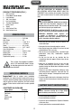
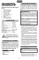
PREPARATION
BATTERY INSTALLATION
1. Pushtabtoopenbatterycompartmentcover(7).
2. Insertbatterieswiththecorrectpolarity.Matchthe(+)
and(-)symbolontheinsideofthecompartmentwith
the corresponding symbol on the batteries.
3. Close the battery compartment cover.
OPERATION
The tool is intended for determining level and plumb
alignment, and checking horizontal and vertical reference
lines.
The tool is designed for indoor use only.
Extreme temperature changes can reduce the accuracy
of the laser. Allow the tool to adjust to the ambient
temperature of the work environment before using. Do not
subjectthelasertoextremelycoldorhotenvironments.
Make reference marks at the center of the laser line.
Turn the tool off when not in use.
SELF-LEVEL LOCk
The tool has a self-leveling function that automatically
levels the laser lines within 5 seconds if the tool is within
±4° of horizontal.
To active the self-leveling function, slide the Self-Level
Lock(1)allthewayupto"ON"position.Thisactivesthe
laser simultaneously. Two crossed laser lines will appear
on the work surface.
TheLevelIndicator(3)onthetopofthetoolindicatesthe
status of the self-leveling function. A green light indicates
the laser line is self-levelled. A red light indicates the laser
line is not self-levelled.
To deactivate the self-leveling function, slide the Self-
Level Lock down to "OFF" position. It will turn the tool off.
POWER / MODE SELECTOR BUTTON
ThePower/ModeSelectorButton(2)islocatedonthetop
of the tool.
The tool has three laser line patterns: Crossed, 360°
Horizontal and Vertical. The laser line pattern can be
selected when either self-levelling is ON or OFF.
When the Self-Level Lock is ON, the laser has been
already activated and the Power/Mode Selector Button is
for selecting the laser line pattern only. Press the Power/
Mode Selector Button repeatedly to choose the desired
laser line pattern.
When the Self-Level Lock is OFF, the tool can be turned on
by pressing the Power/Mode Selector Button. Repeatedly
press the button to select the laser line pattern or turn
the tool off.
SELF-LEVELING MODE
To Set the Tool in Self-Leveling Mode:
1. Place the tool on a flat and solid support or to a tripod.
2. Slide the Self-Level Lock "ON" to activate the self-
leveling function. Two crossed laser lines will appear
on the work surface.
3. Check the Leveling Indicator. If it is green, the self-level
function is at work. If it is red and the laser lines are
flashing, the tool is outside of the ±4° self-leveling
range and will require adjusting until the indicator
appears green.
NON-SELF-LEVELING MODE
The Non-Self-Leveling Mode is for alignment purposes
and for projecting reference laser lines. It cannot be used
to perform leveling functions. In this mode, the Leveling
indicator(3)alwaysappearsred.
To Set the Tool in Non-Self-Leveling Mode:
1. Place the Self-Level Lock in the "OFF" position.
2. PressthePower/ModeSelectorButton(2)toturnthe
tool on. The initial laser projection is crossed laser lines.
You may select other laser line pattern by pressing the
Power/Mode Selection Button repeatedly.
3. Rotate the tool until the desired reference line is
projected on the work surface.
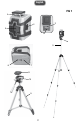
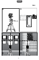
MOUNTING TO A TRIPOD (FIG 2 A)
The tripod provides a stable, height-adjustable support. It
has a Quick Release Plate for fast set-up, and a built-in
level for accuracy.
Tosetupthetripod,extendthelegsapproximate5"below
the desired target height. Level the tripod. The air bubble
on the built-in level bubble vial should be in the center of
the red circle.
AttachtheQuickReleasePlate(9)tothetoolbythreading
the 1/4" screw into the bottom of the tool.
IMPORTANT SAFETY INSTRUCTIONS
OPERATION