
User Guide

1. Installation should be in accordance with acceptable plumb-
ing practices. Flush all piping thoroughly before installation.
Installation and field adjustment are the responsibility of the
installer.
2. Valves are to be installed as close to building inlet supply as pos-
sible to prevent/minimize pressure fluctuations.
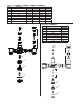
3. Valve body can be rotated to install in multiple position due to
union inlets (see Figure 2). Make sure that union nuts are tight-
ened securely.
4. Connect inlets and outlet and check for leaks.
5. When the Hydroguard supplies tempered water to self-closing
and/or solenoid valves, provide a shock absorber (Powers Part
No. 460-353) on the discharge line.
6. Before use, check discharge temperature. Reset if nec-
essary.
Operation Check:
After Hydroguard is installed, make certain the supply stop valves
and strainers are free and clean and ready for operation by disas-
sembling checkstops as shown in servicing.
Typical Flow
Hot and cold water supplies enter Hydroguard at indicated ports,
(see Figure 1) then flow past their respective balanced poppet plug
and seats. Next, hot and cold water flow is directed to the mixing
chamber where the thermostatic actuator is located.
Temperature adjustment screw moves the actuator to determine the
discharge temperature.
With a rise in discharge temperature due to pressure or tempera-
ture fluctuation on the inlet, the actuator expands, decreasing flow
of hot water. The reverse occurs with a drop in discharge
temperature.
• Cold water supply failure – causes actuator to expand allowing
the motor to drastically reduce hot water flow.
*
• Hot water supply pressure failure – causes actuator to contract
allowing return spring to close cold water port
*
.
*
When tested in accordance to conditions described in ASSE 1017.
Installation Instructions n
Operation n
Figure 2
Back Outlet
Front Outlet
Top Outlet
2
Figure 1
Temperature Adjustment Screw
Temperature Adjustment Locknut
Actuator
Mixing Chamber
Cold Water Seat
Hot Water Seat
Cold Water
Hot Water
Plunger
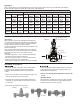
Table 1, Capacity Tables, present the Hydroguard discharge capacity in gpm and l/m for various pressure differentials (the difference
between the lowest inlet pressure and the discharge pressure at the Hydroguard).
Capacity n
* Minimum flow when Hydroguard is installed at or near hot water source with recirculated tempered water with continuously operating recirculating pump.
Flow Capacity at 50-50 mixed ratio
Pressure Drop Across Valve
Model Min.
Min. Flow
5psi 10psi 20psi 30psi 45psi 60psi 70psi
Flow Rate*
to ASSE 1017
CV (34 kPa) (69 kPa) (138 kPa) (207 kPa) (310 kPa) (414 kPa) (517 kPa)
LFMM431
0.5 gpm 3 gpm
6.32
14 gpm 20 gpm 28 gpm 35 gpm 42 gpm 49 gpm 53 gpm
1.89 lpm 11 lpm 53 lpm 76 lpm 106 lpm 132 lpm 159 lpm 185 lpm 201 lpm
LFMM432
0.5 gpm 4 gpm
9.49
21 gpm 30 gpm 42 gpm 52 gpm 64 gpm 74 gpm 79 gpm
1.89 lpm 15 lpm 80 lpm 114 lpm 159 lpm 197 lpm 242 lpm 280 lpm 299 lpm
LFMM433
0.5 gpm 5 gpm
16.44
37 gpm 52 gpm 74 gpm 90 gpm 110 gpm 127 gpm 138 gpm
1.89 lpm 19 lpm 140 lpm 197 lpm 280 lpm 341 lpm 416 lpm 481 lpm 522 lpm
LFMM434
0.5 gpm 7 gpm
21.50
48 gpm 68 gpm 96 gpm 118 gpm 144 gpm 167 gpm 180 gpm
1.89 lpm 26 lpm 182 lpm 257 lpm 363 lpm 447 lpm 545 lpm 632 lpm 681 lpm
LFMM435
0.5 gpm 10 gpm
31.00
69 gpm 98 gpm 139 gpm 170 gpm 208 gpm 240 gpm 259 gpm
1.89 lpm 38 lpm 261 lpm 371 lpm 526 lpm 644 lpm 787 lpm 908 lpm 980 lpm
NOTICE
CAUTION
!