
Operating Temperature Regulators - Sizing Worksheet Owner manual

1. Valve Style
R
■■
Normally Open (air to close)
■■
Double Acting
■■
Normally Closed (air to open)
■■
_________________
■■
Mixing
2. Valve Body Material
R
Process Connection
■■
Bronze
■■
Steel
■■
Screwed
■■
Iron
■■
150# Flanged
■■
Stainless
■■
300# Flanged
■■
______________________
3. Capacity
E/O
Cv Rating_______________________________________________
GPM or #/hr. ____________________________________________
4. Process Load
E/O
• Flow (GPM) of material to be
heated, cooled, or mixed ______________________________
•Temperature increase or decrease
of material ___________________________________________
5. Flow Characteristic and Trim Material
N
■■
Linear
■■
Bronze
■■
Equal %
■■
316 SS
■■
______________________
6. Close Off Requirements
R
■■
Class 2 (leakage to be 0.5% of max. flow or less) [most double seat]
■■
Class 3 (leakage to be 0.1% of max. flow or less)
■■
Class 4 (leakage to be .01% of max. flow or less) [most single seat]
7. Media Through Valve
E/O
■■
Steam
Inlet Pressure
R
________________________________________
Flowing Pressure Drop (∆P)
N
___________________________
■■
Water
Inlet Pressure
R
________________________________________
Flowing Pressure Drop (∆P)
N
___________________________
Temperature
R
_________________________________________
■■
Other
Material Flowing Through Valve _________________________
Inlet Pressure
R
________________________________________
Flowing Pressure Drop (∆P)
N
___________________________
Temperature
R
_________________________________________
7a. Close off differential _________________________________
8. Packing Requirements
N
■■
Service under 300°F
■■
EP V-Ring
■■
Service under 250°F–400°F
■■
Teflon V-Ring
■■
Service 250°–500°F
■■
Graphite
■■
_________________
9. Actuator Requirements
R
• Signal to Actuator
■■
3–15 psi from I/P
■■
1–17 psi from I/P
■■
_______PSI from Positioning Relay
■■
________________PSI from Pneumatic Controller
• Actuator Span
■■
Full Range 3-15 Nominal
■■
Split Range 3–8 psi
■■
Split Range 10–15 psi
■■
Extended Range 0-50 Maximum PSI
10. Accessories
R
■■
Positioning Relay __________________________________
■■
I/P Transducer _____________________________________
■■
I/P and Positioner Combination
■■
Gauge Set
11. Part # _______________________________________________
NOTES
R
Required Information
E/O
Either/Or Information
If the required flow rate through the valve (Capacity, Item #3) is
not known, it can be calculated from the Process Load
Information (Item #4).
N
Nice To Have Information
Pressure drops across the valve can be assumed if they are not
specified by the customer.
Selecting the correct valve size and type is extremely important in order to maintain accurate control and long valve life. To
get the valve that will best meet your needs, please be sure to answer every question noted as “Required” on this Application
Data Sheet.
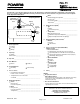
Media Through Valve
Signal
to Actuator
42sq. in.
Flowrite
shown
Process
Load
N.O. & N.C.
Sample Application
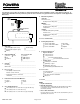
Control Valve
Application Data Sheet
Form ADS#11FW
Flowrite
Page 2 of 2
ADS#11FW 0247 Printed in U.S.A.