TI-593-672 • Up to 1380 lbs. of force • Excellent range control 46” Actuator • Accurate repetitive positioning • Dual NAMUR Accessory Mounts • Field Reversible • “Long-life” design lasts over one million cycles TABLE OF CONTENTS Features . . . . . . . . . . . . . . . . . . . . . . . .2 Description . . . . . . . . . . . . . . . . . . . . .3 Guide to Applications . . . . . . . . . . . . .3 Operation . . . . . . . . . . . . . . . . . . . . . .3 Installing an Actuator . . . . . . . . . . . . .
FEATURES 1. Optional stainless steel springs extend operating life to over one million cycles. 2. Nested spring design creates a uniform stroke by eliminating spring side flex. 3. 316 Stainless steel thrust plate is corrosion resistant. 4. All stainless steel hardware used in combination with SS spring makes long-life standard. 5. Molded fiber and reinforced diaphragm greatly reduces the risk of stress cracks. 6.
DESCRIPTION Powers’ most popular actuator, the ‘46’, is a versatile, field reversible design that is available on most Flowrite II valves. This actuator provides: • large effective area (1380 lbs of force at 30 psi) for powerful valve close control • excellent narrow range control signal performance • accurate repetitive positioning due to large diameter diaphragm, low friction actuator stem and bronze bearings, and • dual NAMUR accessory mounts.
INSTALLING AN ACTUATOR 1. Place actuator assembly over valve stem. With actuator stem and valve stem separated, place bonnet lock nut over valve stem onto bonnet. 2. Apply air pressure to the actuator approximately 9 psi for a Normally Closed valve assembly, and 3 psi for a Normally Open Assembly. 3. Tighten the valve stem to the actuator stem by rotating the valve stem (NOT THE ACTUATOR STEM). 4. Tighten the two locknuts together and rotate them clockwise.
Springs Fig 2C - Remove Diaphragm, Thrust Plate Fig 3A - Typical-Spring Installation CHANGING SPRINGS (REVERSE ACTING ACTUATORS) Springs may be changed with the actuator assembled or removed from the valve. For ease of instruction, pictures are shown with actuators removed. To change or add springs on a Reverse Acting (RA, NC, ATO) actuator assembled to the valve, follow steps 1-4A, 5-8. To change or add springs on a Reverse Acting (RA, NC, ATO) actuator removed to the bench, follow steps: 1-4A, 5-7.
CHANGING ACTION (DIRECT ACTING ACTUATORS) All valve bodies used with Flowrite II Actuators are push-to-close. Directing Acting actuators make the valve action Normally Open (NO, DA, ATC); Reverse Acting actuators make the valve action Normally Closed (NC, RA, ATO). Changing the action of the actuator (DA to RA or RA to DA) will therefore reverse the valve action from NO to NC, or NC to NO.
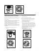
CHANGING ACTION (REVERSE ACTING ACTUATORS) Change Actuator Action from RA to DA: 1. Shut off controlled medium supply (steam, water, or other liquid). 2. Reduce preload on the springs (refer to Decreasing Preload on RA Actuators). 3. Remove the control signal to the actuator. 4. (Fig. 1) Use a 1/2" wrench on the top housing bolts and hold the bottom housing nuts with a 9/16" wrench. 5. (Fig. 2A) Remove upper housing. 6. Remember the orientation of springs on the thrust plate. Remove springs, stem nut (Fig.
PRELOAD The Normally Closed (NC, RC, ATO) valve assembly uses the springs to hold the valve shut, against the upstream pressure attempting to push the plug open. 1. All Normally Closed valve assemblies are factory set to a nominal preload depending on size of 7-10 psi. 2. If your process requires a high air pressure signal (>7 psi) to start the valve moving, it is necessary to decrease the actuator preload.
REPLACING A DIAPHRAGM (DIRECT ACTING ACTUATORS) The diaphragm can be changed with the actuator assembled or removed from the valve. For ease of instruction pictures are shown with actuators removed. To change a diaphragm on a Direct Acting (DA, NO, ATC) actuator assemble to the valve follow steps: 1-4A, 5-9. To change a diaphragm on a Direct Acting (DA, NO, ATC) actuator removed to the bench follow steps: 1-4A, 5-8.
REPLACING A DIAPHRAGM (REVERSE ACTING ACTUATORS) The diaphragm can be changed with the actuator assembled or removed from the valve. For ease of instruction pictures are shown with actuators removed. To change a diaphragm on a Reverse Acting (RA, NC, ATO) actuator assemble to the valve follow steps: 1-4A, 5-10. To change a diaphragm on a Reverse Acting (RA, NC, ATO) actuator removed to the bench follow steps: 1-4A, 5-9.
PARTS LIST - DA ACTUATOR ITEM 1 2 3 4 5 6 7 8 9 10 11 12 13 14 15 16 17 18 19 20 22 23 24 25 PART NUMBER See Chart 672-632A 672-633A See Chart 081-008 080-033 672-646 672-645 672-626 672-627 672-618E 084-015 672-470A 043-009C 082-005R 081-011 080-034 082-005 087-128 672-641 672-620 See Chart 900-326 900-327 CURRENT ACTUATORS 672022D 672033D 672044D 672601D 672602D 672603D 672604D 672605D 672606D 672607D 672651D 672653D 672654D 672655D 672656D 672657D 672666D 672670D 672671D 672672D 672726D 672727D 672728D
PARTS LIST - RA ACTUATOR 19 2 ITEM 1 2 3 4 5 6 7 8 9 10 11 12 13 14 15 16 17 18 19 20 22 23 24 25 PART NUMBER See Chart 672-632A 672-633A See Chart 081-009 080-033 672-645 672-646 672-626 672-627 672-618E 084-015 672-471 043-009C 082-005R 081-011 080-034 082-005 087-128 672-641 672-620 See Chart 900-326 900-327 CURRENT ACTUATORS 672024R 672033R 672044R 672601R 672602R 672603R 672604R 672605R 672606R 672607R 672645R 672651R 672653R 672654R 672655R 672656R 672657R 672666R 672668R 672669R 672670R 672671R
CURRENT ACTUATORS STD 672-642 SPRINGS STD 672-615 SS 672-646 SS 672-645 STEM YOKE LOCK NUT 672-457R 672-461R 672-462R 672-463R 672-464R 672-645R 672-458R 672-644R 0 0 0 0 0 0 0 0 0 0 0 0 0 0 0 0 0 0 0 0 3 0 6 6 4 6 6 6 6 6 6 6 672-634A 672-634A 672-634A 672-634A 672-636A 672-636A 672-634A 672-634A 672-725 672-725 672-725 672-725 672-725 672-724 672-725 672-725 628-008 628-008 628-008 628-008 628-008 628-008 628-008 628-008 SPRING RANGE MATRIX In general, positioners are required to sequence
MODIFICATION DATA TABLES These tables provide actuator design information with regard to the specific valve type and size. Use this information to determine which springs to use, the number of springs required, and spring kit part numbers. These are the correct preload adjustments when mounting an actuator on a valve or changing stems: 5 psi for NO assemblies 7-10 psi for NC assemblies Use these pressure and the "Valve Travel" data to properly adjust the stem length of your actuator/valve assembly.
TABLE 4 VALVE TYPE SS ASSEMBLY VALVE ACTION SIZE NO 1/2 NO 3/4 NO 1 SD NO 1-1/4 NO 1-1/2 NO 2 SP NC 1/2 NC 3/4 NC 1 NC 1-1/4 NC 1-1/2 NC 2 *4X Actuators add 6 Springs #672-645.
TABLE 6 VALVE TYPE SB ASSEMBLY VALVE ACTION SIZE NO 1/2 NO 3/4 NO 1 NO 1 1/4 NO 1 1/2 NO 2 NC 1/2 NC 3/4 NC 1 NC 1 1/4 NC 1 1/2 NC 2 *4X Actuators add 6 Springs #672-645.