This Manual is Bookmarked Operating Instructions and Parts Manual 8-inch Parallelogram Jointer Model PJ-882 WMH TOOL GROUP 2420 Vantage Drive Elgin, Illinois 60123 Ph.: 800-274-6848 www.wmhtoolgroup.com Part No.
This manual has been prepared for the owner and operators of a Model PJ-882 Jointer. Its purpose, aside from machine operation, is to promote safety using accepted operating and maintenance procedures. To obtain maximum life and efficiency from your jointer and to aid in using it safely, please read this manual thoroughly and follow the instructions carefully. Warranty and Service WMH Tool Group warrants every product it sells.
Table of Contents Warranty and Service ..............................................................................................................................2 Table of Contents ....................................................................................................................................3 Warning...................................................................................................................................................5 Introduction.........................
Electrical Connections – 1 Phase, 230 Volt ............................................................................................44 Electrical Connections – 3 Phase, 230 Volt ............................................................................................45 Electrical Connections – 3 Phase, 460 Volt ............................................................................................
Warning 1. 2. 3. 4. 5. 6. 7. 8. 9. Read and understand the entire owners manual before attempting assembly or operation. Read and understand the warnings posted on the machine and in this manual. Failure to comply with all of these warnings may cause serious injury. Replace the warning labels if they become obscured or removed. This jointer is designed and intended for use by properly trained and experienced personnel only.
23. Use the right tool at the correct speed and feed rate. Do not force a tool or attachment to do a job for which it was not designed. The right tool will do the job better and safer. 24. Use recommended accessories; improper accessories may be hazardous. 25. Maintain tools with care. Keep knives sharp and clean for the best and safest performance. Follow instructions for lubricating and changing accessories. 26. Turn off the machine before cleaning.
Introduction This manual is provided by WMH Tool Group covering the safe operation and maintenance procedures for a Model PJ-882 Jointer. This manual contains instructions on installation, safety precautions, general operating procedures, maintenance instructions and parts breakdown. This machine has been designed and constructed to provide years of trouble free operation if used in accordance with instructions set forth in this manual.
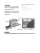
Contents of the Shipping Container Unpacking 1 1 2 1 2 1 1 1 Open shipping container and check for shipping damage. Report any damage immediately to your distributor and shipping agent. Do not discard any shipping material until the Jointer is assembled and running properly. Compare the contents of your container with the following parts list to make sure all parts are intact. Missing parts, if any, should be reported to your distributor.
Installation and Assembly Tools required for assembly Forklift or hoist with straps/slings 14mm (or 9/16”) wrench or socket Cross-point (Phillips) screwdriver 3mm and 5mm hex wrenches (provided) 1. Remove any boards or straps that secure the Jointer to the pallet, and remove protective wrapping. 2. Use a 14mm (or 9/16”) wrench to remove the four lag screws at the base of the stand which helped secure the machine to the pallet. One of these screws is shown in Figure 1.
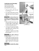
Installing Switch Arm 1. The switch arm was shipped in horizontal position. Loosen and remove the four socket head cap screws and flat washers on the bracket of the switch arm (Figure 3) with a 5mm hex wrench. Hold on to the switch arm while doing this, to prevent the arm from falling. 2. Place the switch arm in vertical position, as shown in Figure 3, and align the four holes in the bracket with the four holes in the jointer stand. 3.
The cutterhead guard should now have sufficient spring tension. Test it by swinging the guard away from the fence and then releasing it. The guard must always have enough spring tension to cover the unused part of the cutterhead during the cutting operation, and to swing back to contact the fence when the workpiece has cleared the area.
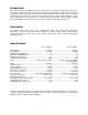
Use only three wire extension cords that have three-prong grounding plugs and three-pole receptacles that accept the tool’s plug. Repair or replace a damaged or worn cord immediately. Make sure the voltage of your power supply matches the specifications on the motor plate of the Jointer. Recommended Gauges (AWG) of Extension Cords Extension cords Extension Cord Length * The use of an extension cord is not recommended for the PJ882 Jointer.
If you are hard-wiring the Jointer, make sure the fuses have been removed or the breakers have been tripped in the circuit to which the Jointer will be connected, and place a warning placard on the fuse holder or circuit breaker to prevent it being turned on until wiring is complete. Converting from 230 Volt to 460 Volt (Three Phase Only) Refer to the diagram on page 46 for connecting the motor leads for 460 volt power.
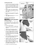
NOTE: After operating the machine for a short time, the drive belt tension should be rechecked, as the new drive belt may stretch slightly during the “breaking-in” period. Drive Belt Replacement 1. Unscrew the knob (A, Figure 11) and remove the belt guard (B, Figure 11). 2. Remove the rear panel (C, Figure 11) by removing the four flat head screws with a cross-point screwdriver. 3. On the motor base plate, loosen the top hex nut (A, Figure 13), and lift up on the motor to create slack in the drive belt.
3. Tighten locking handle (B, Figure 14). To tilt fence backward: The fence can be tilted backward up to 45° (that is, for a total angle of 135° from table surface). 1. Loosen locking handle (B, Figure 16). 2. Flip the 90° stop block (E, Figure 16) out of the way. 3. Rotate handwheel (C, Figure 16) until the desired angle is indicated on the scale (D, Figure 16).
4. Rotate the screw (H, Figure 17) until it contacts the casting in front of it. 5. Tighten the hex nut on the screw (H, Figure 17) and tighten locking handle (B, Figure 16). Setting the 45° Backward Stop 1. The 45° backward stop is controlled by the screw (G, Figure 18), which will contact the back of the fence when the fence is tilted backward. 2. Flip the stop block (E, Figure 18) out of the way. 3. Loosen the locking handle (B, Figure 18) and loosen the hex nut on the screw (G, Figure 18). 4.
2. Knives must be set in the cutterhead so that the highest point of their arc is level with the the outfeed table. 3. Knives must be parallel with the outfeed table across the entire length of the knives. These alignments are explained below. Setting Tables Parallel For optimum performance of the jointer, the infeed and outfeed tables must be parallel frontto-back with each other. If they are not parallel, the finished workpiece may have a slight taper across its width or length.
9. Each table has four cam adjustment devices; two in front and two in back. NOTE: On the front of the Jointer, the two outside cams are concealed by the hubs. You must remove the hub to expose the cam adjustment device. Remove the socket head cap screw and flat washer at the center with a 6mm hex wrench, and loosen the two setscrews in the hub (Figure 21 shows one of the two set screw holes). Pull the hub straight out to expose the cam adjustment device. 10.
When you receive the jointer, the knives have been pre-set at the factory. However, the height and parallelism of the knives with the outfeed table should be checked, and any needed adjustments made, before putting the jointer into operation. Proceed as follows: 1. Disconnect jointer from power source. 2. Place a straight edge upon the outfeed table and extending over the center of the cutterhead as shown in Figures 23 and 24. 3.
Figure 27 illustrates the correct setting of outfeed table level with the knives. The workpiece will rest firmly on both tables with no open space under the finished cut. Figure 27 The outfeed table has now been locked at a standard height, level with the arc of the knives. NOTE: After the outfeed table has been set at the correct height, it should not be changed except for special operations or after replacing knives. Further fine adjustments will now be achieved by adjusting the knives in the cutterhead.
10. Place the aluminum knife gauge at the front of the outfeed table (toward the rabbet ledge) and repeat the process. 11. This test should be performed on all three knives in the cutterhead, using the provided gauge. 12. If any knife is either too high or too low at one of its ends to correctly move the gauge as described above, then the height and/or parallelism of that knife in the cutterhead needs to be adjusted. Proceed as follows. 13.
21. The tightening process should continue at least two more times, each time tightening the gib screws further on all three knives in turn. On the third time, the gib screws should all be firmly tightened. Before operating the jointer, make sure all gib screws are firmly tightened. A loose knife thrown from the cutterhead can cause severe or fatal injury. 22. After all knife adjustments are completed, the guards and fence assembly should be placed back on the machine before operating.
Infeed Table Stop Screws The stop screws below the infeed table have the same function as those for the outfeed table. See “Outfeed Table Stop Screws” for instructions on adjustment. Replacing Knives in the Cutterhead Jointer knives are extremely sharp. Use caution and proceed slowly when working with or around the cutterhead. 1. Disconnect jointer from power source. 2. Remove the belt guard so that you can rotate the cutterhead by turning the motor pulley or by moving the drive belt.
Eliminating “Play” in Tables There are four set screws at the front of the jointer – two on the outfeed table and two on the infeed table – that will allow you to prevent “play” in the tables. (Figure 38 shows a set screw for the outfeed table.) After a period of use, the copper tip (see item #27, page 37) which is attached to the end of the set screw (A, Figure 38) may become loose. Resolve this as follows. 1. Loosen the hex nut (B, Figure 38) with a 14mm wrench. Figure 38 2.
3. The cutterhead guard must be in place and operating properly (except when rabbeting). 4. Infeed table set for desired depth of cut. 5. Stand away from the cutterhead and turn the machine on for a few moments. Listen for any odd noises, rubbings, vibrations, etc. Correct such problems before attempting operations on the jointer. 6. Carefully check your workpiece for knots, holes, staples or any foreign material that might damage knives or pose a risk of kickback.
Rabbeting A rabbet cut requires removal of the guard. Use extreme caution and keep hands clear of cutterhead. Always re-install guard immediately after rabbeting operation is completed. A rabbet is a groove cut along the edge of a board. See Figure 42. The width and thickness of the wood to be rabbeted depends upon the width and length of the rabbet. However, never rabbet a piece of wood less than 12” long. Use push blocks to rabbet cut whenever possible. The rabbeting capacity is 1/2”. Figure 42 1.
Although the fence may be tilted in or out for a bevel cut, it is recommended for safety reasons that the fence be tilted in toward the operator, making a cradled cut. Direction of Grain Avoid feeding work into the jointer against the grain. This may result in chipped and splintered edges. See Figure 44. Feed with the grain to obtain a smooth surface, as shown in Figure 45.
Maintenance Disconnect machine from power source before doing any maintenance. Failure to comply may cause serious injury. The table and fence surfaces must be kept clean and free of rust for best results. Some users apply a thin coat of paste wax. Avoid waxes or protective sprays that contain silicone, as this can transfer to the workpiece and make it difficult for later finishes to adhere to the wood.
Knives can usually be whetted several times in the cutterhead before having to be removed and re-ground. TIP: If the jointer is used frequently, keeping a spare set of knives on hand is recommended. Extra knives (stock no. 6296046, set of 3) may be obtained from your distributor, or by calling customer service at 1-800-274-6848. Cutterhead Repairs The entire cutterhead assembly may be removed from the Jointer for bearing replacement or other maintenance procedures.
Troubleshooting – Operating Problems Trouble Probable Cause Remedy Finished stock is concave on back end. Knife is higher than outfeed table. Raise outfeed table until it aligns with tip of knife. See page 19. Finished stock is concave on front end. Outfeed table is higher than knife. Lower outfeed table until it aligns with tip of knife. See page 19. Finished stock is concave in the middle. Both tables have too much end fall. Raise both table ends using the cam adjustment devices.
Troubleshooting – Mechanical and Electrical Problems Trouble Machine will not start/restart or repeatedly trips circuit breaker or blows fuses. Probable Cause Remedy No incoming power. Verify unit is connected to power, onbutton is pushed in completely, and stop-button is disengaged. See page 24. Overload automatic reset has not reset. When jointer overloads on the circuit breaker built into the motor starter, it takes time for the machine to cool down before restart.
Trouble Machine will not start/restart or repeatedly trips circuit breaker or blows fuses. Probable Cause Remedy Miswiring of the unit. Double check to confirm all electrical connections are correct. Refer to appropriate wiring diagrams on pages 44 through 46 to make any needed corrections. On/off switch failure.
Parts List: Cutterhead Assembly Index No. Part No. Description Size Qty .................PJ882-CHA ............. Cutterhead Assembly (Items 1 thru 5, and 10 thru 13).............................. 1...............6296046.................. Knife.................................................................. ................................... 3 2...............6296153.................. Knife Gib............................................................ ................................... 3 3.........
Parts List: Fence Assembly Index No. Part No. Description Size Qty .................PJ882-FA................ Fence Assembly (Index #1 thru #48).................. ..................................... 1...............PJ882-101 .............. Hand Wheel....................................................... ................................... 1 2...............TS-0267021 ............ Socket Set Screw .............................................. 1/4”-20x1/4” ................ 3 3...............
Fence Assembly 35
Parts List: Outfeed Table and Base Assembly Index No. Part No. Description Size Qty 1...............PJ882-201 .............. Rear (Outfeed) Table ......................................... ................................... 1 2...............6285917.................. Push Block ........................................................ ................................... 2 3...............PJ882-203 .............. Shaft.................................................................. .....................
Outfeed Table and Base Assembly 37
Parts List: Infeed Table Assembly Index No. Part No. Description Size Qty 1...............PJ882-301 .............. Front (Infeed) Table ........................................... ................................... 1 2...............PJ882-302 .............. Scale Label........................................................ ................................... 1 3...............PJ882-203 .............. Shaft.................................................................. ..............................
Index No. Part No. Description Size Qty 56 .............PJ882-246 .............. Key.................................................................... 5x5x20........................ 2 57 .............TS-0209031 ............ Socket Head Cap Screw.................................... 3/8”-16x3/4” ................ 2 58 .............TS-0050031 ............ Hex Cap Screw.................................................. 1/4"-20x3/4” ................ 2 59 .............PJ882-248 ..............
Infeed Table Assembly 40
Parts List: Stand Assembly Index No. Part No. Description Size Qty 1...............VB-A50 ................... Belt.................................................................... A-50 ........................... 1 2...............TS-0267021 ............ Socket Set Screw .............................................. 1/4”-20x1/4” ................ 2 3...............PJ882-503 .............. Motor Pulley ...................................................... ................................... 1 4......
Index No. Part No. Description Size Qty 40 .............TS-081B022............ Pan Head Screw................................................ #8-32x3/8” .................. 4 41 .............PJ882-541 .............. Start Switch ....................................................... ................................... 1 42 .............PJ882-542 .............. Stop Switch ....................................................... ................................... 1 43 .............PJ882-543 .............
Stand Assembly 43
Electrical Connections – 1 Phase, 230 Volt 44
Electrical Connections – 3 Phase, 230 Volt 45
Electrical Connections – 3 Phase, 460 Volt 46
WMH Tool Group 2420 Vantage Drive Elgin, Illinois 60123 Phone: 800-274-6848 www.wmhtoolgroup.