
Owners manual


37
Open
Close
Stop
Common
COM
COM
COM
24V
AC
24V
AC
ALT
RDO
OPN
CRO
FRE
OPN
CLO
STO
COM
CLOSE
PUSH
STOP
PUSH
CLOSE
PHOTO
OPEN
PHOTO
LD16
LD17
LD13
OPEN CLOSE
FORCE
ADJUSTMENT
TB1
U4
COM
COM
COM
24V
AC
24V
AC
ALT
RDO
OPN
CRO
FRE
OPN
CLO
STO
COM
COM
COM
OPN
PHO
CLO
PHO
SHW
REV
OPN
EDG
CLO
EDG
MST
OPN
MST
CLO
COM
COM
COM
OPEN
PUSH
FREE
EXT
ALT
RADIO
OPN/
CLO
RADIO
OPEN
CLOSE
PUSH
STOP
PUSH
CLOSE
PHOTO
OPEN
PHOTO
LD18
LD10
LD11
LD12
LD15
LD14
LD16
LD17
LD13
OPEN
CLOSE
STOP
OPEN CLOSE
FORCE
ADJUSTMENT
AUTO
RECLOSE
TIMER
OFF MAX
MID
LIMIT
REV
LOOP
OPN
EDGE
CLO
EDGE
RH OPN
LH CLO
LIMIT
RH CLO
LH OPN
LIMIT
MOTOR
OPEN
MOTOR
CLOSE
SHADOW
LOOP
LD19
LD2
LD3
LD4
LD5
LD6
LD8
LD9
LD7
12345
POWER
LD1
P3
P4
TB1 TB2
U1
U2
U4
CONTROL CONNECTIONS
CONNECTION OF A THREE-BUTTON STATION:
NOTE: All control contacts must be NORMALLY
OPEN unless dipswitch #3 is placed to the “ON”
position, which will change the circuitry to accept a
NORMALLY CLOSED STOP BUTTON. Refer to Page 35.
1. Connect a wire from the common connection of the
control station to any “COM” terminal on the control
board.
2. Connect a second wire from the “OPEN” button of the
control station to the “OPN” terminal on the control
board.
3. Connect a third wire from the “CLOSE” button of the
control station to the “CLO” terminal on the control
board.
4. Connect a fourth wire from the “STOP” button of the
control station to the “STO” terminal on the control
board.
COM
COM
COM
24V
AC
24V
AC
ALT
RDO
OPN
CRO
FRE
OPN
CLO
STO
COM
COM
COM
OPN
PHO
CLO
PHO
SHW
REV
OPN
EDG
CLO
EDG
MST
OPN
MST
CLO
COM
COM
COM
OPEN
PUSH
FREE
EXT
ALT
RADIO
OPN/
CLO
RADIO
OPEN
CLOSE
PUSH
STOP
PUSH
CLOSE
PHOTO
OPEN
PHOTO
LD18
LD10
LD11
LD12
LD15
LD14
LD16
LD17
LD13
OPEN
CLOSE
STOP
OPEN CLOSE
FORCE
ADJUSTMENT
AUTO
RECLOSE
TIMER
OFF MAX
MID
LIMIT
REV
LOOP
OPN
EDGE
CLO
EDGE
RH OPN
LH CLO
LIMIT
RH CLO
LH OPN
LIMIT
MOT OR
OPEN
MOT OR
CLOSE
SHADOW
LOOP
LD19
LD2
LD3
LD4
LD5
LD6
LD8
LD9
LD7
12
3
4
5
POWER
LD1
P3
P4
TB1
TB2
U1
U2
U4
12
3
4
5
ON
OFF
12
3
4
5
for Normally
Open Stop
Button
ON
OFF
for Normally
Closed Stop
Button
38
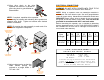
RADIO CONTROL INSTALLATION
A Three or Four wire radio control receiver can be
installed on this operator. See the diagrams below for the
correct connections to match your installations equipment
and desired functions.
1. Choose one of the options below for connecting a
three-wire radio control receiver to the control board
terminal strip.
COM
COM
COM
24V
AC
24V
AC
ALT
RDO
OPN
CRO
FRE
OPN
CLO
STO
COM
STOP
PUSH
CLO SE
PHOTO
OPEN
PHOTO
LD16
LD17
LD13
FORCE
ADJUSTMENT
TB1
U4
COM
COM
COM
24V
AC
24V
AC
ALT
RDO
OPN
CRO
FRE
OPN
CLO
STO
COM
STOP
PUSH
CLO SE
PHOTO
OPEN
PHOTO
LD16
LD17
LD13
FORCE
ADJUSTMENT
TB1
U4
COM
SW.
24 VAC
1
2
3
COM
SW.
24 VAC
1
2
3
Three Wire Radio Reciever
Wired For "OPEN/CLOSE"
Three Wire Radio Reciever
Wired For "OPEN" Only
NOTE: Must Be Used With
Timer to Close Option.
CONNECTION FOR
OPEN/CLOSE OPERATOR
CONNECTION FOR
OPEN/ONLY OPERATOR
2. Choose ONE of the options below for the connection
of a FOUR-WIRE radio control receiver to the control
board terminal strip.
NOTE: If your radio’s connecting wires are not color
coded as shown, see the radio’s installation manual to
determine which wires are for the normally open
contacts and which require the 24 VAC Power Supply.