TABLE OF CONTENTS SAFETY INSTRUCTIONS GENERAL CONSIDERATIONS………………………………………………………………........3 U/L INSTALLATION AND SAFETY CONSIDERATIONS…………………….............….….….4 INSTALLATION CLASS DESCRIPTION……………………………………………………….....4 SYSTEM DESIGNER SAFETY INSTRUCTIONS………………………………........................5 INSTALLER SAFETY INSTRUCTIONS…………………………………………….....................6 END-USER SAFETY WARNINGS…………………………………………………………...........9 MANUAL DISCONNECT OPERATION…………………………………………………….........
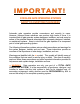
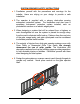
IMPORTANT! FOR SLIDE GATE OPERATING SYSTEMS SAFETY IS EVERYONE’S BUSINESS Automatic gate operators provide convenience and security to users. However, because these machines can produce high levels of force, it is important that all gate operator system designers, installers, and end users be aware of the potential hazards associated with improperly designed, installed, or maintained systems. Keep in mind that the gate operator is a component part of a total gate operating system.
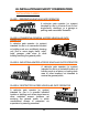
U/L INSTALLATION AND SAFETY CONSIDERATIONS INSTALLATION CLASSES CLASS I – RESIDENTIALVEHICULAR GATE OPERATOR A vehicular gate operator (or system) intended for use in a home of one to four single-family dwellings, or a garage or parking area associated therewith.
SYSTEM DESIGNER SAFETY INSTRUCTIONS Ÿ 1. Familiarize yourself with the precautions and warnings for the installer. Users are relying on your design to provide a safe installation. Ÿ 2. The operator is supplied with a primary obstruction sensing entrapment protection system. The installation must also have a secondary entrapment protection system installed, such as photoelectric sensors or an electric edge system. Ÿ 3.
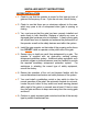
INSTALLER SAFETY INSTRUCTIONS BEFORE INSTALLATION Ÿ 1. Check to see that the operator is proper for this type and size of gate and its frequency of use. If you are not sure, consult factory. Ÿ 2. Check to see that there are no structures adjacent to the area, which may pose a risk of entrapment when gate is opening or closing. Ÿ 3. You must ensure that the gate has been properly installed and works freely in both directions. Replace or service any worn or damaged gate hardware prior to installation.
DURING INSTALLATION Ÿ 1. Be aware of all moving parts and avoid close proximity to any pinch points. Ÿ 2. Disconnect power at the control panel before making any electric service connections. Connection location for controls and safety equipment can be found on the wiring diagram, and in this manual. Ÿ 3. Know how to operate the manual disconnect mechanism. Ÿ 4. Adjust the open and close force adjustment on the control board in each direction to the minimum force required to operate the gate smoothly.
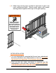
Ÿ 6. Attach large warning signs provided to each side of gate in the most conspicuous place. Mount control station and smaller warning placard together within sight of the gate opening. WARNING Moving Gate Can Cause Serious Injury or Death. KEEP CLEAR! Gate May Move at Any Time. Children Should Not Operate Gate. Operate Gate Only When Area is in Sight and Free of People and Obstructions.
END-USER SAFETY WARNINGS The manufacturer of the gate operator does not know what type of gate you have, or what type of automatic system is installed on your gate. Be sure you’ve been fully instructed on the sequence of operation for your specific gate system(s). Keep the gate properly maintained and have a qualified service person make repairs. Ÿ 1. Be sure the following safety instructions are distributed to all persons authorized to use your gate. Ÿ 2. KEEP GATEWAY CLEAR (Front and Back) AT ALL TIMES.
Ÿ 3. DO NOT allow children to play near your gate, or to operate the gate. Ÿ 4. DO NOT operate your gate system unless you can see it when the gate moves. Ÿ 5. Be sure a pushbutton or key switch has been installed for manual electric operation in the event your radio or card does not work. Any mounted control station should be located a minimum of 10 feet from the gate so the gate cannot be reached through or touched. Any pushbutton located in a building should be installed within sight of the gate.
Ÿ 7. If your gate has open rollers, be sure roller guards have been purchased and installed.
Ÿ 8. Your gate system is required to have a primary and a secondary entrapment safety system installed and maintained. Ÿ 9. If your gate closes automatically, loop detectors should be installed to detect the presence of a vehicle. Ÿ 10. DO NOT increase force adjustment to compensate for a damaged gate. The gate should always be maintained to operate manually as easily as possible to provide maximum protection. Ÿ 11.
SAFETY WARNINGS FOR OPEN-ROLLER GATES AND ORNAMENTAL GRILLE-TYPE GATES Ÿ WARNING: INJURIES ASSOCIATED WITH AUTOMATIC GATES ARE MAINLY INCURRED WITH OPEN-ROLLER GATES AND ORNAMENTAL “GRILLE TYPE” GATES. OPEN-ROLLER GATES Ÿ Injuries occur when people get their hands caught between the top of the gate and the roller. This potential pinch point should be guarded whenever an automatic operator is installed. Roller Guards are available from various fence suppliers for refitting of these rollers.
INSTALLATION INSTRUCTIONS Ÿ WARNING: DO NOT APPLY POWER UNTIL TOLD TO DO SO! RISK OF ELECTRICAL SHOCK OR INJURY MAY RESULT! BEFORE INSTALLING OPERATOR IMPORTANT: Operator should always be mounted inside the gate. Determine whether the installation is Left hand or Right hand by the direction the gate moves in order to open, when viewed from inside the fence. PUBLIC AREA OR STREET PUBLIC AREA OR STREET RIGHT HAND LEFT HAND 1. Gate must slide freely to fully opened and fully closed position. 2.
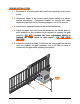
INSTALLATION OF CEMENT PAD Lay out the cement pad as shown. Be sure top surface is level. Allow 2 days cure time before installing operator. Bolt pattern must be parallel to the gate. Min. Side Room Required = Gate Opening +A +B +36" A Gate Opening 36" Min. B 8" Fence Gate 3" Gate Bracket 1 CL 2 20-1/2" Ref Of Drive Chain 1/2" Mounting Hardware (6) Places ( Not Supplied). 2-1/2" Ref Electrial Conduit 1 1" 3-3/4" Ref 10-3/4" 10-3/4" 2 Install Chain Support Bracket As Required.
INSTALLATION TO PAD 1. Using ½” hardware (Not Supplied) bolt assembled unit to the pad, being sure to align operator parallel to the fence. NOTE: Sprockets must face the fence. Drive Chain FENCE Cement Pad Conduit Depth As Required By Local Code 28" Min. 25-1/2" Min.
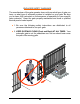
ATTACHING DRIVE CHAIN 1. Install gate brackets at each end of the gate with U-bolts provided. Do not fully tighten at this time. 2. Attach a chain take up bolt to one end of the drive chain using a #50 connecting link. 3. Install spring fittings into gate brackets using ¾” nuts and lock washers. DO NOT tighten. 4. Install chain take up bolt, previously attached to the chain, into spring fitting in furthest gate bracket. Secure it in position with spring, spring washer, and ½” elastic stop nut.
Gate Leading Edge Gate Extension Gate Bracket Chain Support Bracket Gate Bracket Drive Chain Cement Pad Nut Spring Washer Chain Support Back up plate 1/2-13 Elastic Stop Nut Chain Support Bracket Chain Tensioning Spring Bolt Spring Fitting 3/8" U-Bolts Gate Bracket Install Chain Support Brackets As Required Washer 3/4 Internal Tooth Lock Washer Nut 3/4-10 Jamb Nut Chain take-up Bolt #50 Connecting Link 5.
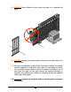
7. Pull the chain through to the opposite end of the gate. Cut the chain to the correct length, attach remaining chain take-up bolt and install in the gate bracket as in steps 2 through 4. 8. Adjust the gate bracket height at both ends of the gate to insure the drive chain aligns with the operator idler sprockets. 9. Tighten the gate brackets securely and lock in position with the setscrews provided.
NOTE: By moving the gate manually to each end of its travel, chain alignment is simplified. Jamb Nut 11. Adjust chain tension so that the chain tension springs are reduced to a length within 1-7/8” and 1-3/4”.
Ÿ ELECTRICAL SET-UP AND CONNECTIONS CONNECTION OF INCOMING POWER WARNING: DO NOT APPLY POWER UNTIL TOLD TO DO SO! RISK OF SHOCK OR INJURY MAY RESULT. NOTE: Before connecting the operator to an incoming power supply, use a voltmeter to determine that the electrical service is the same as that on the operator label. If the operator is connected to an incorrect power supply, damage will result, which is NOT covered by warranty. Ÿ 1. Be sure the power switches at source, and at the operator are OFF. Ÿ 2.
INSTALLATION OPTIONS LEFT/RIGHT HAND CONVERSION: Determine the hand of the operator required for this installation by checking the direction the gate moves in order to open, when viewed from inside the fence. Slides RIGHT to open is a right hand installation, slides Left to open is a left hand installation.
NOTE: This unit is factory setup for RIGHT HAND operation. To convert operator to left hand operation move dipswitch #2 to on position.
3. Connect a wire from the “MST OPN” terminal on the Master operators control board, to the “OPN” terminal on the Slave operators control board. 4. Connect a second wire from the “MST CLO” terminal on the Master operators control board, to the “CLO” terminal on the slave operators control board. 5. Connect a third wire from any “COM” terminal on the Master operators control board, to any “COM” terminal on the Slave operators control board.
EMERGENCY CONTROL STATION OPTION Provision has been made to change the control station operational mode to one that would only be activated when the entrapment sensing system is in stop mode; with the warning horn activated. This would give a person access to control the gate in an emergency situation, but it would be inoperative under normal circumstances. To activate this option, move dipswitch #1 to the “ON” position.
TIMER TO CLOSE OPTION The operator is equipped with a timer to close option for use with OPEN ONLY control devices such as a radio control, or card key control. The AUTO RECLOSE TIMER adjustment screw is located on the printed circuit board. The operator is shipped from the factory with this timer preset to the off position; fully counter clockwise. As the timer adjustment screw is rotated clockwise, the closing of the gate can be delayed from 2 seconds to 60 seconds.
AUDIBLE PRE - MOVE WARNING By moving Dipswitch #4 to the “ON” position the option of a 3 second Audible Warning, before gate movement, may be selected.
AUXILIARY CIRCUIT FOR USE WITH GATE LOCKS, WARNING LIGHTS, ETC An auxiliary 24 VAC power circuit, for use with a 24V control relay, has been provided. This circuit will be activated just prior to gate movement and will continue to be active until the gate stops. It may be used to control a gate lock, activate warning lights and solenoid controlled devices or any other system required during this time interval. Two control options are available.
OPTION #2 – POWER SUPPLIED DURING GATE MOVEMENT The following diagram shows the connection of a device, such as a solenoid operated gate lock, requiring power during gate movement. Power In To Aux. Device Neutral Power leg Relay With 24 VAC Coil To Gate Locks, Warning Lights, Ect. N.C. N.O.
LIMIT ADJUSTMENT PROCEDURE Ÿ WARNING: TURN OFF MAIN POWER BEFORE MAKING ANY ADJUSTMENTS! 1. After the gate is mechanically installed, disengage operator drive with the manual disconnect lever. Move the gate to a midway position. NOTE: When moving the gate with the operator disengaged, the limit nuts on the limit assembly inside the operator can be driven passed their normal position.
2. With the gate at mid travel, depress the pressure plate and set the grooved limit nuts approximately 1 inch from the limit switches on each side. 3. Check that Dipswitch #2 is in the correct position for left or right hand operation as determined by the location of the gate opener, when viewed from inside the fenced area.
Ÿ WARNING: STAY CLEAR OF ALL MOVING PARTS AND ELECTRICAL COMPONENTS OF THE OPERATOR WHILE TESTING! NOTE: The first time the gate operator is run after the power is turned on; a 3 second warning will sound before the operator starts. 5. Open the gate electrically using the THREE BUTTON control station mounted on the control board.
7. If the operator runs in the wrong direction proceed to step #9. 8. If the limit nut depresses the open limit switch but does not stop the gate, press the stop button or turn off the power immediately, and consult factory. (1-800-243-4476). 9. Check position of dipswitch #2 to be sure it coincides with the installation. (Left Hand or Right Hand) If this is correct and operator is 1Ø consult the factory. (1-800-243-4476). 10.
NOTE: Open and Close Limit Switches are Reversed for slide left to Open Operation. Limit nut Limit switch housing Pressure Plate Limit nut OPEN LIMIT SWITCH For Slide Right To Open Operation CLOSE LIMIT SWITCH for slide right to open operation 16. After the desired open and close position of the gate has been obtained, make certain that a groove in both limit nuts are engaged by the pressure plate.
1. Connect a wire from the common connection of the control station to any “COM” terminal on the control board. 2. Connect a second wire from the “OPEN” button of the control station to the “OPN” terminal on the control board. 3. Connect a third wire from the “CLOSE” button of the control station to the “CLO” terminal on the control board. 4. Connect a fourth wire from the “STOP” button of the control station to the “STO” terminal on the control board.
RADIO CONTROL INSTALLATION A Three or Four wire radio control receiver can be installed on this operator. See the diagrams below for the correct connections to match your installations equipment and desired functions. 1. Choose one of the options below for connecting a threewire radio control receiver to the control board terminal strip. CONNECTION FOR OPEN/CLOSE OPERATOR LD16 CONNECTION FOR OPEN/ONLY OPERATOR LD16 U4 STOP PUSH LD17 LD17 OPEN PHOTO OPEN PHOTO LD13 COM 2 SW.
2. Choose ONE of the options below for the connection of a FOUR-WIRE radio control receiver to the control board terminal strip. NOTE: If your radio’s connecting wires are not color coded as shown, see the radio’s installation manual to determine which wires are for the normally open contacts and which require the 24 VAC Power Supply.
LOOP DETECTOR SYSTEMS AND INSTALLATION The diagram below depicts the typical loop options for a Slide Gate installation. 1. The Exit Loop provides a signal to open the gate when a vehicle enters the loop zone. 2. The Reversing Loops protect a vehicle in the loop zone from being contacted with the gate by overriding any close signal while the gate is open, and by reversing the gate if closing.
LOOP INSTALLATION 1. Layout the desired loop locations per the diagram. The standard size chart below will give an approximate length of wire required for various loop dimensions and number of turns required. CAUTION: The Loop wires and Lead-in wires must be a continuous piece of wire without splices. Only use wire intended for this type of application. (Type XHHW insulation 16AWG) NOTE: Buried steel from drains or other systems may affect functioning of the loop system.
2. Cut the required groove as shown in the diagram below at the locations laid out in Step #1. Loop Wire (See Chart) Lead In Wire (Twisted At 6 Turns Per Foot) 1/2" Conduit Conduit Cut 3/16" To 1/4" 1" To 2" 1" To 2" 3. Leaving enough wire for the LEAD IN, insert the specified number of turns of wire in the cut grooves. (See chart). CAUTION: Be careful not to damage the wire insulation during installation. 4.
7. Mount the loop detector in the operator and connect the wire loop. 8. Connect loop detector to the control board as shown in the following diagrams. EXIT LOOP CONNECTION LD16 U4 STOP PUSH LD17 OPEN PHOTO LD13 CLOSE PHOTO COM STO CLO OPN FRE CRO V OR R P Not Used BK BL ALT RDO OPN 24V AC 24V AC COM COM Y WH COM FORCE ADJUSTMENT TB1 TO DRIVEWAY LOOP BR GY GR NOTE: TWIST LEADS APPOX. 6 TURNS PER FOOT.
SAFETY DEVICE CONNECTIONS INHERENT OBSTRUCTION SENSING DEVICE: NOTE: The gate MUST move smoothly and easily in manual operation before attempting this adjustment. TURN OFF POWER TO OPERATOR WHEN MAKING WARNING: ANY ADJUSTMENTS. This unit is supplied with a speed sensing system, which will stop the gate when it encounters an obstruction and then backs the gate off approximately 2 inches.
SECONDARY OBSTRUCTION SENSING DEVICES Another sensing device (Either a contact or a non-contact system) must be installed and connected to this unit to increase protection against entrapment per U/L requirements. NOTE: All safety device contacts must be NORMALLY OPEN. NOTE: 24 VAC power is available at marked terminals for devices that may require it (i.e., photo eyes, wireless edges, etc). CONTACT SENSOR INSTALLATION: NOTE: Wireless sensors must be installed so there is no signal interference.
2. Connect contact sensor edges to the control board as shown in the illustration below. CONTACT SENSOR CONNECTION Leading Edge MAX LD7 COM SHADOW LOOP COM OPN EDG CLO EDG MST OPN MST CLO REV 1 2 3 4 5 COM OFF Trailing Edge NOTE: Leading edge is connected to “CLO EDG” and “COM” terminals. Trailing edge, Post Mounted edge and Fence Mounted edge are connected to “OPN EDG” and “COM” terminals. 3. After sensors are mounted and electrically connected, turn on the power. 4.
NON-CONTACT SENSOR INSTALLATION 1. Install photoelectric cell as close to inside of gate as possible. 2. Photocells should be installed across the gate opening and behind the gate (as shown below) at least 10 inches above ground. NOTE: A separate pedestrian gate must be installed if there is no other entry access but the vehicular gate.
3. Connect NON-CONTACT sensors to the control board as shown below. NON CONTACT SENSOR CONNECTION Reflector Close Photocell Sensor Reflector Open Photocell Sensor SHW OPN PHO CLO PHO COM COM COM STO CLO OPN TB2 NOTE: Close photocell is connected to “CLO PHO” and “COM” terminals. Open photocell is connected to “OPN PHO” and “COM” terminals. AFTER SENSORS ARE CONNECTED: 1. Turn on power. 2. Make sure the photo-beams are properly aligned per the manufacturer’s specifications. 3 .
WIRING TO 2004 UMCB-01 CONTROL BOARD To Control Relay Aux. Control Circuit For Gate Lock, Warning Lights, Etc.
LED AND DIP SWITCH INFORMATION FOR 2004 UMCB-01 CONTROL BOARD P3 P4 LD1 POWER LD18 LD19 MID LIMIT OPEN PUSH LD10 FREE EXT LD11 LD2 U2 REV LOOP LD3 OPEN OPN EDGE ALT LD4 LD12 CLO EDGE CLOSE LD5 RH OPN LD15 RADIO OPEN LH CLO LIMIT STOP LD6 RH CLO LD14 CLOSE PUSH OPEN CLOSE LH OPN LIMIT U1 LD16 LD8 U4 STOP PUSH MOTOR OPEN AUTO RECLOSE TIMER LD17 OPEN PHOTO LD9 OFF LD13 LD7 DIPSWITCHES S1 - OFF = NORMAL OPEN/CLOSE PB ON = SAFETY/SECURE MODE S2 - OFF = RIGHT HAND ON = LEFT H
PowerMaster Limited 5 Year Warranty PowerMaster warrants all gate operators to be free of defects in materials and workmanship for a period of Five (5) years from date of purchase. If any part is found to be defective during this period, new parts will be furnished free of charge. Failure of this product due to misuse; improper installation, alterations, vandalism, or lack of maintenance are not covered under this warranty, and voids any other implied warranties herein.
NOTES __________________________________________________________ __________________________________________________________ __________________________________________________________ __________________________________________________________ __________________________________________________________ __________________________________________________________ __________________________________________________________ __________________________________________________________ __________________________________
MAINTENANCE SUGGESTIONS Lubricate the drive chain and idler sprocket bearings every 3 months with 30-weight oil. Grease the drive shaft bearings every 6 months with quality grade automotive grease. The Reducer is completely sealed and should not require lubrication. Periodically check all hardware (nuts, bolts, screws, etc) for tightness.
R&S Automation 7200 E. 92nd Avenue Unit A Portland, OR 97266 877-388-4001 503-771-4685 Fax 503-774-6708 John Greene Corp. 2807 Center Circle Drive Downers Grove. IL 60515 800-374-7890 Fax 630-627-7995 Oregon rk New Yo Illinois Texas Fl or id a R & S Automation Inc. 15075 Wicks Blvd San Leandro, CA 94577 800-543-6001 510-357-4110 Fax 510-483-1326 R & S Automation Inc. 1560 N. Missle Way Anaheim, CA 92801 800-963-3111 714-449-1645 Fax 714-449-1679 Power Door Products 610 Fenimore Rd.