
Owner's Manual
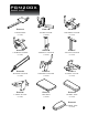


PGM200X
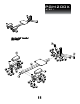
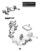
STEP 3
BE CAREFUL TO ASSEMBLE ALL COMPONENTS
IN THE SEQUENCE THAT THEY ARE PRESENTED.
NOTE:
finger tighten all hardware FIRST in this step. wrench tighten all
hardware at the END of step 3F. some components may be pre-assembled.
nylon lock nuts will not fully screw onto bolts, must wrench tighten.
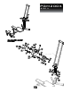
3A. lay the two glide bars of sliding frame (G) on a flat
surface and affix connect frame (H) in the center of
the glide bars of sliding frame (G).
3B. position four 35mm rollers (#8) between r-foot plate (J)
and connect frame (H) and secure this assembly using
a total of:
4 - (#34) M8X40mm hex head bolt
8 - (#51) M8 washer
4 - (#41) M8 nylon lock nut
8 - (#60) M12 spacer
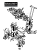
3C. position four 35mm rollers (#8) between l-foot plate (K)
and connect frame (H) and secure this assembly using
a total of:
4 - (#34) M8X40mm hex head bolt
8 - (#51) M8 washer
4 - (#41) M8 nylon lock nut
8 - (#60) M12 spacer
3D. attach the entire assembled sliding frame (G) to
base frame (B) using:
2 - (#30) M10X55mm hex head bolt
4 - (#50) M10 washer
2 - (#40) M10 nylon lock nut
14