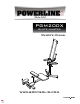
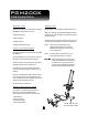
PGM200X GLUTE MASTER Owner’s Manual WWW.BODYSOLID.
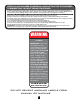
THERE IS A RISK ASSUMED BY INDIVIDUALS WHO USE THIS TYPE OF EQUIPMENT. TO MINIMIZE RISK, YOU MUST FOLLOW THESE RULES: Inspect equipment before each workout. Check that all nuts, bolts, screws and pop pins are in place and fully tightened. Also, before use, check cables for sign of wear. Replace all worn parts immediately. Never use machine if any parts are damaged or missing. FA IL U R E T O F O L L O W T H E S E R U L E S M AY RESULT IN SERIOU S INJURY.
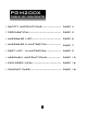
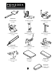
PGM200X TABLE OF CONTENTS • SAFETY INSTRUCTIONS....................... PAGE 4 • PREPARATION....................................... PAGE 5 • HARDWARE LIST................................... PAGE 6 • HARDWARE ILLUSTRATION................. PAGE 7 • PART LIST / ILLUSTRATION.................. PAGE 9 • ASSEMBLY INSTRUCTIONS................. PAGE 10 • EXPLODED VIEW................................... PAGE 16 • CONTACT PAGE.....................................
PGM200X SAFETY INSTRUCTIONS • When using exercise equipment, you should always take basic precautions including the following: The PGM200X is designed for your enjoyment. By following these precautions and using common sense, you will have many safe and pleasurable hours of healthful exercise with your Powerline Glute Master. Read all instructions before using the PGM200X. These instructions are written to ensure your safety and to protect the unit.
PGM200X PREPARATION Required tools Assembly Tips The basic tools that you must obtain before assembling the PGM200X include but are not limit to: Read all “Notes” on each page before beginning each step. • Standard Wrench Set While you may be able to assemble the PGM200X using the illustrations only, important safety notes and other tips may be included in the text. • Metric Wrench Set • Adjustable Wrench Some pieces may have extra holes that you will not use.
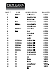
PGM200X HARDWARE LIST PART # SIZE DESCRIPTION 6 QUANTITY
, 7 , PGM200X ¨w¿®z®>P°¸>®¨zÅ^ HARDWARE ILLUSTRATION Part #30 M10X55mm hex head bolt QTY. 6 Part #31 M10X60mm hex head bolt QTY. 2 Part #32 M8X40mm hex head bolt QTY. 2 Part #33 M8X20mm hex head bolt QTY. 8 Part #34 M8X50mm hex head bolt QTY. 8 Part #40 M10 nylon lock nut QTY.
, 7 , PGM200X ¨w¿®z®>P°¸>®¨zÅ^ HARDWARE ILLUSTRATION CONT. Part #41 M8 nylon lock nut QTY. 8 Part #43 M10 nut QTY. 1 Part #50 M10 washer QTY. 16 Part #51 M8 washer QTY. 26 Part #54 M10 spring washer QTY.
PGM200X PART LIST PartA PartB PartC mainframe base frame r-elbow frame [1pcs] [1pcs] [1pcs] PartD PartE PartF l-elbow frame vertical frame adjust frame [1pcs] [1pcs] [1pcs] PartG PartH PartJ sliding frame connect frame r-foot plate [1pcs] [1pcs] [1pcs] PartK PartL PartM l-foot plate leg pad chest pad [1pcs] [1pcs] [1pcs] PartN 9 elbow pad [1pcs]
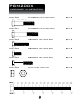
PGM200X STEP 1 BE CAREFUL TO ASSEMBLE ALL COMPONENTS IN THE SEQUENCE THAT THEY ARE PRESENTED. NOTE: finger tighten all hardware in this step. DO NOT wrench tighten until the last step. some components may be pre-assembled. nylon lock nuts will not fully screw onto bolts, must wrench tighten. 1A. insert a oval end cap into the front opening of mainframe (A) and side openings of base frame (B) using: 3 - (#1) 40X80mm oval end cap 1B.
PGM200X STEP 1 11
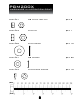
PGM200X STEP 2 BE CAREFUL TO ASSEMBLE ALL COMPONENTS IN THE SEQUENCE THAT THEY ARE PRESENTED. NOTE: finger tighten all hardware in this step. DO NOT wrench tighten until the last step. some components may be pre-assembled. nylon lock nuts will not fully screw onto bolts, must wrench tighten. 2A. attach vertical frame (E) to mainframe (A) using: 2 - (#30) M10X55mm hex head bolt 4 - (#50) M10 washer 2 - (#40) M10 nylon lock nut note: adjust hole position as necessary to accomodate your personal body height.
PGM200X STEP 2 13
PGM200X STEP 3 BE CAREFUL TO ASSEMBLE ALL COMPONENTS IN THE SEQUENCE THAT THEY ARE PRESENTED. NOTE: finger tighten all hardware FIRST in this step. wrench tighten all hardware at the END of step 3F. some components may be pre-assembled. nylon lock nuts will not fully screw onto bolts, must wrench tighten. 3A. lay the two glide bars of sliding frame (G) on a flat surface and affix connect frame (H) in the center of the glide bars of sliding frame (G). 3B.
PGM200X STEP 3 15
PGM200X EXPLODED VIEW 16
PGM200X NOTES 17
PGM200X please write your serial number in the boxes below S/N # - - - - Body-Solid b Built for Life 1900 1900S. S.Des DesPlaines PlainesAve. Ave. Forest ForestPark, Park,IL IL60130 60130 Phone:(708)427-3555 Phone:(708)427-3555 Fax:(708)427-3556 Fax:(708)427-3556 Hours: Hours:M-F M-F8:30 8:30- -5:00 5:00CST CST www.bodysolid.com 2011. Body-Solid. All rights reserved. Body-Solid reserves the right to change design and specifications when we feel it will improve the product.