Active Archive Appliance (A3) Racking and Installation Guide v6.
951-13035-04 A3 Racking and Installation Guide v6.5 20 October 2008 Copyright ©2006, 2007, 2008 PowerFile, Inc. All Rights Reserved. This work contains trade secrets and confidential material of PowerFile, Inc., and any use or disclosure in whole or in part without the express written permission of PowerFile, Inc., is prohibited. Reproduction in any manner whatsoever without the written permission of PowerFile, Inc. is strictly forbidden.
Contents About This Guide . . . . . . . . . . . . . . . . . . . . . . . . . . . . . . . . . . . . . . . . . . . . . . . . . . . . . . . . . . . v Purpose. . . . . . . . . . . . . . . . . . . . . . . . . . . . . . . . . . . . . . . . . . . . . . . . . . . . . . . . . . . . . . . . . . . . . v Audience . . . . . . . . . . . . . . . . . . . . . . . . . . . . . . . . . . . . . . . . . . . . . . . . . . . . . . . . . . . . . . . . . . . v Related Documents . . . . . . . . . . . . . . . . . . . . . . . . . . .
iv CONTENTS Determining the Archive Engine Model . . . . . . . . . . . . . . . . . . . . . . . . . . . . . . . . . . . . . . . . . . . 7 Installing the Archive Engine (Generation 1) . . . . . . . . . . . . . . . . . . . . . . . . . . . . . . . . . . . . . . . 8 Identifying the Rail Kit Hardware . . . . . . . . . . . . . . . . . . . . . . . . . . . . . . . . . . . . . . . . . . . . . 8 Attaching the Inner Rail to the Chassis and the Outer Rails to the Rack . . . . . . . . . . . . . .
v CONTENTS Front Panel HDDs and LEDs. . . . . . . . . . . . . . . . . . . . . . . . . . . . . . . . . . . . . . . . . . . . . . . . . . . 56 7 Setting Up the A3 System . . . . . . . . . . . . . . . . . . . . . . . . . . . . . . . . . . . . . . . . . . . . . . . . . . 57 In This Chapter. . . . . . . . . . . . . . . . . . . . . . . . . . . . . . . . . . . . . . . . . . . . . . . . . . . . . . . . . . . . . . Connecting the Archive Engine and Media Libraries . . . . . . . . . . . . . . . . . . . . . . . . .
vi Active Archive Appliance (A3) v6.
About This Guide Purpose The Active Archive Appliance (A3) Racking and Installation Guide explains how to install the Archive Engine, Media Library, and Cache Expansion Array in a rack. Audience This guide is intended for professional system integrators and PC technicians. Installation and maintenance should be performed by experienced technicians only.
vi Active Archive Appliance (A3) v6.
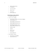
1 Introduction In This Chapter • • • Archive Engine (Generation 1) Archive Engine (Generation 2) Media Library (Generation 2 or Generation 3) The A3 system consists of the Archive Engine and one or more Media Libraries. The two hardware components of your A3 system function best when they are mounted in standard IT racks. This chapter provides an overview of the A3 system shipping components and safety precautions.
2 Introduction • 8 M5x12 Pinhead Screws • 8 Lock Washers • 1 Torx Screwdriver • 2 Power Cords • 1 Front Bezel • User Documentation Archive Engine (Generation 2) • • • PowerFile Archive Engine Accessory box containing: • 2 Inner Rails Pre-attached to Server (Left and Right) • 2 Inner Rail Extensions • 4 M5x10 Phillips Pan Head Screws • 2 M5x24 Phillips Pan Head Screws • 4 M3x6 Phillips Flat Head Screws • 8 M5x16 Phillips Flat Head Screws • 10 M5 Cage Nuts • 8 Washers • 2 Po
3 Introduction Media Library (Generation 2 or Generation 3) • • • PowerFile Media Library Rail Kit box containing: • 2 Outer Rails (Left and Right) • 2 Inner Rails (Left and Right) packed in Outer Rails Accessory box containing: • Registration Card • Product Information Brochure • Warranty Card • 1 1394 FireWire Cable • 1 Power Cord • 2 Qualification Media Discs (Generation 3 only) Note: Do not open the Media Library unit. There are no user-serviceable parts inside the unit.
4 Introduction Electrical Distribution System Precautions • The rack should have a safe electrical distribution system. It must provide overcurrent protection for the unit and must not be overloaded by the total number of units installed in the rack. Consideration of the electrical power consumption rating shown on the nameplate should be used when addressing these concerns. • • The electrical distribution system must provide reliable grounding for each unit in the rack.
2 Preparing for Installation In This Chapter • • • • Unpacking the A3 System Preparing for Setup Choosing a Setup Location Rack Mounting Considerations This chapter provides information about how to prepare for installing the A3 system. Unpacking the A3 System Unpack the Archive Engine and Media Library shipping boxes. Ensure that you have all required components. Refer to “A3 System Shipping Components” on page 1 for the shipping inventory list.
6 Preparing for Installation Choosing a Setup Location • Leave enough clearance in front of the rack to enable you to open the front door completely (~25 inches). • Leave approximately 30 inches of clearance in the back of the rack to allow for sufficient airflow and ease in servicing. • This product is for installation only in a Restricted Access Location (dedicated equipment rooms, service closets and the like).
3 Installing the Archive Engine In This Chapter • • • Determining the Archive Engine Model Installing the Archive Engine (Generation 1) Installing the Archive Engine (Generation 2) This chapter provides instructions for installing the Archive Engine, Generation 1 and Generation 2. Note: The following installation procedures apply to standard Electronics Industries Association (EIA) racks. Non-EIA racks may not be able to support the Archive Engine.
8 Installing the Archive Engine Installing the Archive Engine (Generation 1) The rails are shipped together, with the inner rail located inside the outer rail.You’ll need to separate the two rails and then attach the inner rails and latches to the Archive Engine prior to mounting the device into the rack. The rails are attached with the screws provided in the shipping box. The rack must be assembled with the left and right chassis components correctly oriented.
9 Installing the Archive Engine Table 3-1 Archive Engine (Generation 1) Rail Kit Hardware (Continued) Hardware Active Archive Appliance (A3) v6.5 Name Quantity Use Allen Wrench 1 Attaching the chassis latches to the inner rail. M5x12 Flathead Screw 8 Securing outer rails into rack (front and rear). Use with ATX rail slide washers. ATX Rail Slide Washer (Square Hole) 8 Securing outer rails in a square hole rack. ATX Rail Slide Washer (Round Hole) 8 Securing outer rails in a round hole rack.
10 Installing the Archive Engine Table 3-1 Archive Engine (Generation 1) Rail Kit Hardware (Continued) Hardware Name Quantity Use Lock Washers 8 Securing outer rails in a tapped hole rack with M5x12 Pinhead Screw. (For Tapped Hole Racks). Torx Screwdriver 1 Locking drives in Archive Engine chassis. Attaching the Inner Rail to the Chassis and the Outer Rails to the Rack This section explains how to attach the inner rails to the chassis and the outer rails to the rack.
11 Installing the Archive Engine To attach the inner rails: 1. Attach C to the left and right side of the chassis using screws E with the Allen wrench. Repeat this step on the other side of the chassis. The inner rail is attached by four screws on each side. Note their relative positions in the diagram. L Latch stop E F G C Archive Engine (Generation 1) 2. Attach F to the left and right slides using screws G. Ensure the latch F is oriented with its spring arm located against its stop.
12 Installing the Archive Engine Left-hand assembly shown Clamping screws Round hole rack Rear rack post J Rail kit can be adjusted to fit racks of sizes (between internal faces). Minimum: 685mm, Maximum 889mm h d Front rack post Archive Engine Rail Assembly (Generation 1) Active Archive Appliance (A3) v6.
13 Installing the Archive Engine 3. (Perform this step only if installing into a tapped hole rack) Remove the nut as shown using supplied spanner K. Note: This step starts the instructions for installing the outer rails.
14 Installing the Archive Engine 4. Find the location pin at the rear end of the rail and use the Allen wrench to tighten it into the rear rack post. Extend the rail to fit between the front and rear rack posts. Make sure that the front and rear mount points are at the exact same height. 5. Secure the outer rails to the rack from the front and rear using the screws and washers provided. Repeat this step on the other side of the chassis.
15 Installing the Archive Engine Installing the Archive Engine (Generation 2) The Archive Engine package includes two rack rail assemblies in the rack mounting kit. Each assembly consists of an inner fixed chassis rail that secures directly to the server chassis, inner rail extensions, and an outer slide rack rail that secures directly to the rack itself. Inner Rail Extensions Rail Locking Tabs Inner Rails (Attached to Chassis) Archive Engine (Generation 2) Both chassis rails have a locking tab.
16 Installing the Archive Engine Identifying the Rail Kit Components Table 3-3 identifies the rail kit hardware for the Archive Engine (Generation 2). Table 3-3 Archive Engine (Generation 2) Rail Kit Hardware Hardware Name Quantity Use M5x10 Phillips Pan Head Screw 4 Attach the extension bracket to the short bracket M5x24 Phillips Pan Head Screw 2 Hold the server in the rack. M3x6 Phillips Flat Head Screw 4 Secure the inner rail extension to the Archive Engine.
17 Installing the Archive Engine To attach the inner rail extensions: 1. Place the inner rail extensions A on the side of the Archive Engine aligning the hooks of the chassis with the rail extension holes. Make sure the extension faces “outward” just like the preattached inner rail. B A Archive Engine (Generation 2) Inner Rail Assembly Detail 2. Slide the inner rail extension toward the front of the Archive Engine B. 3.
18 Installing the Archive Engine Attaching the Outer Rails The outer rails attach to the server rack and hold the server in place. The outer rails for the Archive Engine extend between 32 inches and 34 inches (or up to 40 inches with the extension). To attach the outer rails: 1. Assemble the outer rail by attaching the short section of the rail to the outside of the long section of the rail. You must align the pins with the slides. Also, both bracket ends must face the same direction. 2.
19 Installing the Archive Engine Attaching the Extension Brackets If you have an extended depth rack, extension brackets can be added to the end of the rails to increase the length of the outer rails by 6 inches up to 40 inches. To attach the extension brackets to the rack: 1. Assemble the outer rail by attaching the short section of the outer rail to the outside of the long section of the outer rail. You must align the pins with the slides. Ensure that the bracket ends face the same direction. 2.
20 Installing the Archive Engine 5. Secure the extension bracket to the rear side of the rack with two of the M5x10 screws and the provided washers. The extension bracket has threaded holes, so no nuts are needed. 6. Repeat steps for the other extension bracket. Mounting the Archive Engine in the Rack To mount the Archive Engine in the rack: 1. Confirm that the Archive Engine has the inner rails A and rail extensions B attached. Also, confirm that the outer rails C are installed on the rack.
21 Installing the Archive Engine 4. (Optional) Insert the two M5x24 screws on either side of the server, and then tighten to hold the server in the rack. 5. (Optional) If the drives were shipped in the Archive Engine, PowerFile recommends that you unlatch and reseat the drives before powering on the server. When performing this step, ensure that you do not replace the drives in the wrong slots. That is, make sure you replace the drives back in their original slots; don’t swap the drives around. 6.
22 Active Archive Appliance (A3) v6.
4 Installing the Media Library in a Front-mount Configuration In This Chapter • • • • • • • Front-mount Configuration Getting Started Setting Up the Front-mounted Chassis Installing the Inner Slide Rails on the Front Mounted Chassis Installing the Outer Rails on the Front-mounted Chassis Installing the Chassis in the Rack Attaching the Media Library Feet This chapter explains how to mount and install the Media Library in a front-facing configuration in the rack.
24 Installing the Media Library in a Front-mount Configuration Getting Started To get started: 1. Before beginning the rack installation procedure, decide where you want to install the Media Libraries in the rack. Note: Due to the length of the connecting cables, you need to install the Archive Engine toward the middle of the rack, with the Media Libraries installed above and below the Archive Engine. 2. Remove all the components from the Media Library kit.
25 Installing the Media Library in a Front-mount Configuration 2. Loosen the keyhole screws C and D on the right and left side of the chassis. D C Media Library Keyhole Screws The pre-installed keyhole screws must be loosened to allow proper mounting of the inner rails. Active Archive Appliance (A3) v6.
26 Installing the Media Library in a Front-mount Configuration Installing the Inner Slide Rails on the Front Mounted Chassis To install the inner slide rails: 1. Install the inner slide rails over the bottom keyhole screws in the direction indicated by the arrow. Repeat this step on the other side of the Media Library. Media Library Inner Slide Rails and Keyhole Screws 2. Tighten the keyhole screws. 3.
27 Installing the Media Library in a Front-mount Configuration Media Library Inner Slide Rail and Self-tapping Screws Installing the Outer Rails on the Front-mounted Chassis The outer rails attach to the server rack and hold the server in place. The outer rails for the Media Library extend between 30 inches and 42 inches. No tools are required to attach the outer rails. To install the outer rails: 1.
28 Installing the Media Library in a Front-mount Configuration Outer Rail Inner Slide Rail Media Library Inner Slide Rail on Front-mount Configuration 2. Adjust the rail to the proper distance so that it fits between the front and rear rack posts. 3. At the rear of the rack, position the rail so that one of the white mounting-bracket flanges rests against the inside of the rack post. Active Archive Appliance (A3) v6.
29 Installing the Media Library in a Front-mount Configuration Refer to the following figure for the location of the white mounting-bracket flanges on the outer rail. There is one mounting-bracket flange on each end of the outer rail. Mounting-bracket Flanges on Outer Rail See the following figure for a close-up picture of the mounting-bracket flange.
30 Installing the Media Library in a Front-mount Configuration Mounting-bracket Flange (Attached) 4. Line up the two pins to the appropriate RMU holes on the rack, and then gently push the rail into place. The mounting-bracket flange will lock automatically in the rack post. 5. On the rack's front vertical post, identify the RMU location where you want to attach the rail. 6.
31 Installing the Media Library in a Front-mount Configuration 8. Repeat Step 1 through Step 7 for the left outer rail. 9. To install multiple chasses, repeat steps Step 1 through Step 8 for each front-facing chassis you plan to install in the rack. Make sure to leave enough vertical room between rail pairs to accommodate the height of a 5 RU media library. Installing the Chassis in the Rack To install the chassis: 1.
32 Installing the Media Library in a Front-mount Configuration 3. On the left outer rail, locate the rail latch. Push down on the rail latch. Media Library Rail Latch Refer to the following illustration for a close up of the rail latch. Media Library Rail Latch (Close Up) 4. Locate the rail latch on the right outer rail. Pull up on the rail latch. 5. Slide the Media Library rails into the rack rails, keeping the pressure even on both sides. 6.
33 Installing the Media Library in a Front-mount Configuration Media Library in Front-mount Configuration Attaching the Media Library Feet Some Media Library models are shipped with the feet already attached. Follow the steps below if your library does not have the feet attached and you wish to place the Media Library unit on a flat surface instead of installing it on a rack. Your PowerFile Library Accessory Kit contains four (4) feet that can be attached to the bottom of the Media Library.
34 Installing the Media Library in a Front-mount Configuration 5. Use the supplied screws to attach the four feet to the Media Library base. Media Library Feet Note: If you choose to attach the feet to the Media Library, you must attach all four feet. Active Archive Appliance (A3) v6.
5 Installing the Media Library in a Back-to-Back Configuration In This Chapter • • • • • • • • • Back-to-Back Configuration Getting Started Setting Up the Front-mounted Chassis Installing the Inner Slide Rails on the Front Mounted Chassis Setting Up the Rear-mounted Chassis Installing the Inner Slide Rails on the Rear-mounted Chassis Installing the Outer Rails on the Front-mounted Chassis Installing the Outer Rails on the Rear-mounted Chassis Installing the Chasses in the Rack This chapter provides instr
36 Installing the Media Library in a Back-to-Back Configuration • Install the Archive Engines in the middle of the rack, between two or more Media Libraries. This accommodates the length of the cable connections to the Media Libraries. For example, one Archive Engine should face the back and the other should face the front. • Install two inner rails on each Media Library; one on the right side and one on the left side of the chassis.
37 Installing the Media Library in a Back-to-Back Configuration Back-to-Back Configuration Getting Started To get started: 1. Before beginning the rack installation procedure, decide which Media Libraries will be installed front-facing in the rack, and which ones will be installed rear-facing in the rack. Note: Be sure to take into consideration the installation of a 2RU Archive Engine in the middle of the rack, between two or more Media Libraries. 2.
38 Installing the Media Library in a Back-to-Back Configuration Setting Up the Front-mounted Chassis To set up the chassis: 1. Remove the self-tapping screws A and B on the right and left side of the chassis. Save the four screws. You’ll need them in a later step. B A Media Library Self-tapping Screws Active Archive Appliance (A3) v6.
39 Installing the Media Library in a Back-to-Back Configuration 2. Loosen the keyhole screws C and D on the right and left side of the chassis. D C Media Library Keyhole Screws The pre-installed keyhole screws must be loosened to allow proper mounting of the inner rails. Active Archive Appliance (A3) v6.
40 Installing the Media Library in a Back-to-Back Configuration Installing the Inner Slide Rails on the Front Mounted Chassis To install the inner slide rails: 1. Install the bottom inner slide rails over the keyhole screws in the direction indicated by the arrow. Repeat this step on the other side of the Media Library. Media Library Inner Slide Rails and Keyhole Screws 2. Tighten the keyhole screws. 3.
41 Installing the Media Library in a Back-to-Back Configuration Media Library Inner Slide Rail and Self-tapping Screws Setting Up the Rear-mounted Chassis To set up the chassis: 1. Remove the self-tapping screws A and B on the right and left side of the chassis. Save the four screws. You’ll need them in a later step. B A Media Library Self-tapping Screws Active Archive Appliance (A3) v6.
42 Installing the Media Library in a Back-to-Back Configuration 2. Loosen the keyhole screws C and D on the right and left side of the chassis. D C Media Library Keyhole Screws The pre-installed keyhole screws must be loosened to allow proper mounting of the inner rails. Active Archive Appliance (A3) v6.
43 Installing the Media Library in a Back-to-Back Configuration Installing the Inner Slide Rails on the Rear-mounted Chassis To install the inner slide rails: 1. Install the bottom inner slide rails over the keyhole screws in the direction indicated by the arrow. Repeat this step on the other side of the Media Library. Media Library Inner Slide Rails and Keyhole Screws 2. Tighten the keyhole screws. 3.
44 Installing the Media Library in a Back-to-Back Configuration Installing the Outer Rails on the Front-mounted Chassis The outer rails attach to the server rack and hold the server in place. The outer rails for the Media Library extend between 30 inches and 42 inches. No tools are required to attach the outer rails. To attach the outer rails: 1. On the rack's rear vertical post, identify the RMU location where you want to attach the right outer rail.
45 Installing the Media Library in a Back-to-Back Configuration Mounting-bracket Flanges on Outer Rail See the following figure for a close-up picture of the mounting-bracket flange. Mounting-bracket Flange (Close Up) When attached, the prongs on the mounting-bracket flange wrap around the rail and insert in the screw holes to secure the rail in place. Active Archive Appliance (A3) v6.
46 Installing the Media Library in a Back-to-Back Configuration Mounting-bracket Flange (Attached) 4. Line up the two pins to the appropriate RMU holes on the rack, and then gently push the rail into place. The mounting-bracket flange will lock automatically in the rack post. 5. On the rack's front vertical post, identify the RMU location where you want to attach the rail. 6.
47 Installing the Media Library in a Back-to-Back Configuration 8. Repeat Step 1 through Step 7 for the left outer rail. 9. To install multiple chasses, repeat steps Step 1 through Step 8 for each front-facing chassis you plan to install in the rack. Make sure to leave enough room between the rails to accommodate the stacked 5 RU chasses. Installing the Outer Rails on the Rear-mounted Chassis The outer rails attach to the server rack and hold the server in place.
48 Installing the Media Library in a Back-to-Back Configuration Refer to the following illustration for the location of the white mounting-bracket flanges on the outer rail. There is one mounting-bracket flange on each end of the outer rail. Mounting-bracket Flanges on Outer Rail See the following figure for a close-up picture of the mounting-bracket flange. Mounting-bracket Flange (Close Up) Active Archive Appliance (A3) v6.
49 Installing the Media Library in a Back-to-Back Configuration When attached, the prongs on the mounting-bracket flange wrap around the rail and insert in the screw holes to secure the rail in place. Mounting-bracket Flange (Attached) 4. Line up the two pins to the appropriate RMU holes on the rack, and then gently push the rail into place. The mounting-bracket flange will lock automatically in the rack post. 5.
50 Installing the Media Library in a Back-to-Back Configuration 8. Repeat Step 1 through Step 7 for the left outer rail. 9. To install multiple chasses, repeat steps Step 1 through Step 8 for each front-facing chassis you plan to install in the rack. Make sure to leave enough room between the rails to accommodate the stacked 5 RU chasses. Installing the Chasses in the Rack To install the chasses: 1.
51 Installing the Media Library in a Back-to-Back Configuration 3. Locate the rail latch on the outer left rail. Push down on the rail latch. Media Library Rail Latch Refer to the following illustration for a close up of the rail latch. Media Library Rail Latch (Close Up) 4. Locate the rail latch on the right outer rail. Pull up on the rail latch. 5. Slide the Media Library rails into the rack rails, keeping the pressure even on both sides. Active Archive Appliance (A3) v6.
52 Installing the Media Library in a Back-to-Back Configuration 6. Push the Media Library until it is fully inserted into the rack and it locks into place. The Media Library should glide smoothly on the rails. Rear-mounted Chassis Front-mounted Chassis Media Libraries in Back-to-Back Configuration Active Archive Appliance (A3) v6.
6 Installing the Cache Expansion Unit In This Chapter • • • • Identifying the Rail Kit Components Before You Begin Attaching the Mounting Brackets and Rails Front Panel HDDs and LEDs This chapter provides instructions for installing the Cache Expansion Unit in the rack. Up to two Cache Expansion Units can be installed per one Archive Engine. Note: The following installation procedures apply to standard Electronics Industries Association (EIA) racks.
54 Installing the Cache Expansion Unit Identifying the Rail Kit Components The Cache Expansion Unit package includes two fixed rails, two rear-mounting brackets, and a set of screws. If your rack requires cage nuts, you’ll need to provide these yourself. Table 6-1 Cache Expansion Unit Rail Kit Hardware Hardware Name Quantity Use Phillips Pan Head Screw 8 Attaching rear mounting brackets to rear rack posts. Phillips Flat Head Screw 10 Attaching rails to chassis.
55 Installing the Cache Expansion Unit Before You Begin Do not install the 12 1-TB HDD into the Cache Expansion Unit before installing the chassis in the rack. You will install the hard disk drives into the chassis after it is installed in the rack. Attaching the Mounting Brackets and Rails To attach the mounting brackets and rails: 1. Attach each rear mounting bracket to a rear rack post using two of the provided pan head screws. The side of the bracket with the long slot should be oriented inward.
56 Installing the Cache Expansion Unit Front Panel HDDs and LEDs The HDD bays are identified from top to bottom and then left to right (from enclosure front side) as #1 to #12. HDD Bays and LEDs Table 6-2 describes these LEDs. Table 6-2 Front Panel LEDs Component LED System Power (PWR) • Blue LED On: System powered on. • Blue LED Off: System has no power. System Status (FAIL) • Red LED On: System has a fault.
7 Setting Up the A3 System In This Chapter • • • • • Connecting the Archive Engine and Media Libraries Connecting Cache Expansion Arrays Powering On the A3 System Loading Qualification Media in Media Library (Generation 3) Powering Off the A3 System This chapter provides instructions for setting up the A3 system after all components have been mounted in the rack.
58 Setting Up the A3 System The following steps require the use of cables and connectors that have been supplied as part of the PowerFile Archive Engine or Media Library package. To connect the Archive Engine and Media Libraries: 1. Use an Ethernet cable to connect the Archive Engine to the network. There are two ports on the back of the unit. Only one of the ports should be connected to the network for initial setup.
59 Setting Up the A3 System A b Archive Engine and Media Library Connections • If more than one Media Library is installed at your site, it is recommended that you distribute the Media Libraries among the FireWire cards. For example, given four libraries, plug one library into each card before you start doubling up. • If using a back-to-back configuration, connect all front-facing Media Libraries to the frontfacing Archive Engine.
60 Setting Up the A3 System Connecting Cache Expansion Arrays Up to two Cache Expansion Arrays can be connected to one Archive Engine. You use the RAID controller cables supplied with the Cache Expansion Array to connect the I/O module on the Cache Expansion Array to the RAID controller on the Archive Engine. All connections are made to the back of the chasses. The following illustration shows the Cache Expansion Array connectors on the I/O module.
61 Setting Up the A3 System A b c d Two Cache Expansion Arrays and Archive Engine Connections Active Archive Appliance (A3) v6.
62 Setting Up the A3 System Connecting One Cache Expansion Array to an Archive Engine To connect one Cache Expansion Array to an Archive Engine: 1. Connect A on the RAID Controller card of the Archive Engine to b (UP2) on the I/O module of the Cache Expansion Array. A b One Cache Expansion Array and Archive Engine Connections Active Archive Appliance (A3) v6.
63 Setting Up the A3 System Powering On the A3 System The individual components of the A3 System should be powered on in the following order: • • • Power on all Media Libraries Power on all Cache Expansion Arrays Power on the Archive Engine Powering On the Media Library To ensure proper initialization, always power on the Media Libraries prior to powering on the Archive Engine. To power on a library, press the power button located on the lower left front corner of the library.
64 Setting Up the A3 System AC Receptacles Power Switch Cache Expansion Array Power Connectors Powering On the Archive Engine (Generation 1) Once the Media Libraries are powered on, and the LCDs display a message similar to “PowerFile Archive Library,” power on the Archive Engine (Generation 1) by pressing the power button located on the back of the chassis. It will take the Archive Engine 3-5 minutes to discover and initialize all external devices.
65 Setting Up the A3 System Powering On the Archive Engine (Generation 2) Once the Media Libraries and optional Cache Expansion Arrays are powered on, and the Media Library LCDs display a message similar to “PowerFile Archive Library,” power on the Archive Engine (Generation 2) by pressing the power button located on the front of the chassis. It will take the Archive Engine 3-5 minutes to discover and initialize all external devices.
66 Setting Up the A3 System Powering Off the A3 System The individual components of the A3 System should be powered off in the following order: • • • Power off the Archive Engine Power off all Cache Expansion Arrays Power off all Media Libraries Refer to “Powering On the A3 System” on page 7–63 for the location of the power buttons on these components. Active Archive Appliance (A3) v6.
Contacting PowerFile If you have specific comments or questions about PowerFile solutions that have not been addressed in this document, please check our FAQ or fill out our Information Form. This will help us to learn a little about you, and will give you an opportunity to send us your comments and questions. Sales / Product / General Questions U.S. Inquiries: (866) 838-3669 International Inquiries: (650) 403-9214 9:00 a.m. - 5:00 p.m. Pacific Time Zone sales@powerfile.
951-13035-04 A3 Racking and Installation Guide v6.