
Spec Sheet


Enclosed Scroll Air Compressor System
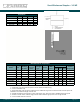
SEH, SEO – 30-40 HP
Powerex • 150 Producon Drive • Harrison, OH 45030 • USA
P 1.888.769.7979 • F 513.367.3125 • www.powerexinc.com
01/2017
Page 1 of 2
Specicaon
General
The Powerex Enclosed Scroll Air Compressor System is designed
to provide clean, dry air for applicaons where the quality of the
compressed air is crical. The standard unit is rated for a maximum
of 115 PSIG. A high pressure version (max. 145 PSIG) is also available.
Air Compressor System
The package shall include mulple oil-less scroll air compressors
and associated equipment. The only eld connecons required will
be system intake if remote intake opon is chosen, exhaust, and
power connecon at the control panel.
Oilless Scroll Compressor Pump
Each compressor pump shall be belt driven oil-less rotary scroll
single stage, air-cooled with absolutely no oil needed for operaon.
The rotary design shall not require any inlet or exhaust valves within
the compressor pump housing or structure and shall be rated for
100% connuous duty. Direct drive compressors shall not be used. Tip
seals shall be of a composite PTFE material and be rated for 10,000
hours operaon (5,000 hours for high pressure version). Compressor
pump bearings shall be external to the air compression chamber
and pin crank and moving scroll bearings shall be serviceable for
extended compressor life. Bearing maintenance shall not be required
unl 10,000 run hours (5,000 run hours for high pressure version).
Compressor pumps with bearings that are not accessible for service
have a limited life span and shall not be accepted. Compressor pumps
shall have an integral radial ow fan for cooling. Each compressor
pump shall have exible connectors on intake and discharge. Each
compressor pump shall have a non-metallic heat insulang liner for
the discharge air pipe where it threads into the compressor housing.
Each compressor pump shall be provided with an electric drive
motor, discharge check valve, an air-cooled aer-cooler, and a high
discharge temperature shut down switch. Auxiliary cooling fans shall
operate from 120 volt power provided by the transformer included in
the system controls.
Motor
Each compressor shall be belt driven by a 4 pole, TEFC, NEMA
construcon motor. Motors running at speeds higher than 1800 RPM
shall not be acceptable. Motors are EISA compliant and premium
ecient.
System Controls
The controls operate the six or eight air compressor modules as
needed in response to a pressure signal from a pressure transducer
located in the system manifold. An illuminated on/o push buon
controls power to the motor starters. When the buon is in the o
posion, the system is merely in stand-by mode, not powered o.
The pressure transducer sends a signal to the programmable
logic controller (PLC) which is programmed to operate six or eight
compressor modules as needed to maintain the system pressure
requirements. An HMI touch screen interface displays system status
and alarm condions. Pressure sengs are user adjustable within
factory predetermined seng limits.
The PLC will alternate each compressor module based on demand
as well as med alternaon. If a compressor module is running longer
than ten minutes connuously, the control will alternate to the next
available compressor module to equalize run me and synchronize
maintenance intervals. On inial start up or if air pressure drops
rapidly, simultaneous motor starts are prevented by a programmed
three second stagger. One 120VAC control circuit transformer with
primary and secondary fuses is installed for control circuit voltage.
Motor circuit breakers with lockable disconnects are provided for
each compressor module. Operang hours, high temperature alarms,
motor overload alarms, run indicaon, and hours to scheduled
maintenance for each compressor module are displayed on the
screen. All alarm history is kept in the alarm log. Easily navigated
menus are provided to allow the user to select the display condions
and acknowledge the alarms. Remote alarm contacts are provided as
shown on the system wiring diagram.
Inlet Filters
The system includes two inlet lters, each with a pleated element
and a canister with silencing tubes. Each inlet lter serves half the
compressor modules in the system. Each lter is located inside the
sound reducing cabinet protected by a convenient access panel.
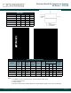
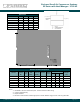
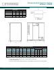
Sound Reducing Enclosure
The system is constructed with an internal frame and steel base
system with individual vibraon isolaon mounted compressor
modules. The sound reducing enclosure has a front access panel to
allow service of the electrical controls. The enclosure has rear cooling
air intake and all exhaust air leaves the enclosure from the top.
Oponal Desiccant Air Dryer
The twin-tower desiccant dryer(s) shall be sized for the peak
calculated system demand to provide a pressure dew point of 0°F.
Dryer controls shall include a re-pressurizaon cycle to prevent
shocking of the desiccant bed prior to switching towers. An integral
purge saving control system shall be provided and shall suspend the
purge air loss during periods of low demand. When the dryer is in
purge control mode, the tower switching valves shall not operate,
and only one desiccant tower shall be on-line. Dryers that connue to
operate the switching valves on a xed cycle, while in purge control
mode shall not be acceptable. (Dryers ulizing purge control require
the oponal dew point monitor listed below.) Each dryer is supplied
with two stages of ltraon. The pre-lter removes parculates and
liquids and includes an element change indicator and automac
condensate drain. The 0.5 micron aer lter includes an element
change indicator. Dryers shall be powered through a separate control
circuit and not through the compressor controls.
Oponal Refrigerant Air Dryer
The refrigerated air dryers are non-cycling, direct expansion type,
using R-134 A refrigerant (CFC free). A hot gas by-pass system maintains
a consistent temperature at all load condions. Heat exchangers are