
manual


POWER BOX Evolution 40/16
- 9 -
This measure is necessary because there are servos available on the market fitted
with electronic circuitry which does not prevent reverse voltage.
Certain receiver types are also not protected against this potential problem.
The design of our PowerBoxes ensures that you can use any type of servo and
receiving system.
In this case the ferrite rings fitted to the backer cables are not only designed to
provide additional RF suppression, since the integral servo signal amplifiers already
fulfil this task reliably. The ferrite rings de-couple the earth (ground) between
receiver and backer. This ensures that the operating conditions for the receiver are
exactly the same as those for which the radio manufacturer originally set up the
unit.
In practical terms the receiver’s earth surfaces represent the earth base, i.e. the
counterbalance to the aerial.
The earthing conditions should not be altered by more than a particular amount,
because this would have an adverse effect on the optimum tuning of the receiver.
That is the reason why each connecting lead of our battery backer systems is fitted
with a ferrite ring.
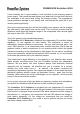
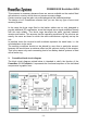
3. PowerBox block circuit diagram
The block circuit diagram printed below is intended to clarify the function of the
PowerBox 40/16 Evolution. It represents the functional sequence of the individual
components in graphic form: