
manual
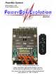


POWER BOX Evolution 40/16
- 5 -
This is in direct contrast with other manufacturers’ products which contain no
duplicated components - as required for a truly secure system - even though they
are powered by two batteries. You have selected a product which offers genuine
duplication of systems (system redundancy) in the interests of your safety. We
believe it is important to emphasise this particular point, as we and most serious
modellers accept it as a fundamental necessity that any device which is responsible
for safety in an aircraft should always be present in a duplicated, or redundant form.
This is precisely the approach taken by the PowerBox 40/16 Evolution.
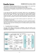
The PowerBox 40/16 Evolution also provides you with “remote access” for up to
five channels from the receiver. We have coined this term because we are
absolutely convinced - and countless tests have confirmed our conviction - that not
all receiver channels should be operated using an external power supply. Why
should that be? Well, there is nothing fundamentally wrong with the standard
receiver sockets, and they are always adequate for certain servos and model
functions. Even so, there are particular applications in model aircraft for which it is
not good practice to use the standard receiver connections.
That is why we recommend that you set up “remote access” to certain channels
from the receiver; the channels concerned are these:
1. Channels which are required to control multiple servos (several servos per
control surface; hence integrated signal amplification required);
2. Channels which are operated using very long servo leads (more than 60 cm;
hence integrated servo signal amplification, also RF suppression);
3. Channels which have to supply extremely powerful, high-performance servos
with correspondingly high current drain (digital servos, Jumbo servos, Power
servos), in order to reduce the load on the receiver;
4. Channels which require special interference suppression measures
(RF suppression of long servo leads, turbine electronics, flasher units, throttle
servo, ignition servo, and many more);
5. Channels which are operated constantly when a normal model is in flight, e.g.
aileron, elevator and rudder; this reduces the load on the receiver.
All the other servos of your receiving system (flaps, retracts, aero-tow release etc.)
can be connected to the appropriate receiver socket in the usual way. Which of the
channels you “access remotely” from the receiver is up to you, but it is usually
those mentioned above.
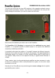
The backer (battery change-over switch) function is based on an extremely high-
performance 40 Amp Dual Schottky diode; both diodes are housed in their own
case. This diode arrangement ensures that voltage losses in operation are
extremely low (0.25 Volt).