
manual


POWER BOX Evolution 40/16
- 12 -
Charging these batteries is as simple as charging a mobile phone!
Naturally, each battery set includes a practical mount and accessories.
Of course, it is possible to connect two separate receivers to this battery backer. If
you wish to do this be sure to observe the information supplied by your RC
manufacturer concerning the use of two receivers in a model, otherwise there may
be problems with interaction between the two units (minimum physical separation
20 cm).
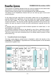
Power is supplied to the receivers via the five servo leads of the PowerBox 40/16
Evolution.
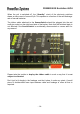
In the centre of the top panel of the PowerBox 40/16 Evolution you will find two
polarised sockets. To each of these you can connect an ultra-bright red LED for
each battery via the extension lead; the LEDs are supplied in the accessory pack.
These LEDs can be mounted in the fuselage side of your model. When the
aeroplane is in the air, these LEDs provide you with a visual warning if one or both
batteries should run flat, or if some other fault should occur in the power supply
system.
If you see the LEDs light up, please land the model immediately. We recommend
that you install both LEDs as close together as possible, as this doubles the
effective strength of the light output, making it easier to pick out in the air.
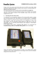
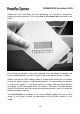
Install the battery backer in the model aircraft with adequate vibration protection, as
used for the other components of the receiving system. You will find that the
mounting plate with its four screw-holes makes it easy to install the backer.
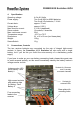
7. The SensorSwitch
The purpose of the SensorSwitch is to provide external control of the integral
electronic switches in our PowerBox 40/16 Evolution.
The SensorSwitch does not switch the current for the servos and receiver. The
actual switching process is carried out by the two completely independent electronic
switches inside the battery backer.
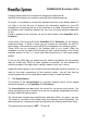
The switch plate houses three push-buttons and three LEDs: two green, one red.
The switch is mounted on the model using two retaining screws (supplied). The
plate features two countersunk holes through which the retaining screws are fitted.
The push-buttons are marked “SET”, “I” and “II”.