
User manual PowerBox Professional


www.powerbox-systems.com 7
Note: The residual capacity of the two batteries as displayed on the screen
is likely to drift apart as the packs are discharged; this is due to minor dif-
ferences in the rate of discharge of the batteries through the PowerBox.
This by no means indicates a fault in the PowerBox; in fact it proves that
the system features genuine redundancy. Here at PowerBox Systems we
take great trouble to compensate for manufacturing tolerances between
the two regulators, but it is never possible to produce a system which
is completely devoid of tolerances. The only method of discharging two
batteries at 100 % identical rates is to use a system tted with only one
regulator. However, such systems cannot be claimed to offer redundancy!
- Graphic indicator of battery charge state:
This display is set to match the capacity you previously entered for the bat-
teries connected to the backer. Assuming that the battery is of good quality,
this means: if the bar only reaches the half-way point, then the battery is
still half-full.
- Operating time:
This gure shows the elapsed time since the last RESET. It is important
always to carry out a RESET after each battery charge process.
- Output voltage:
This value displays the backer’s exact output voltage. The voltage fed to the
servos and receiver is the exact value displayed here.
3.4 AFTER THE CHARGE PROCESS
The PowerBox must be reset after each charge process, otherwise it is im-
possible for the unit to display reliable values for energy consumption and
operating times. The latest software release detects a charging process and
resets the capacity counters automatically.
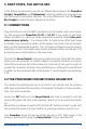
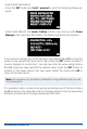
The capacity counters can be reset ma-
nually: With the system switched on, lo-
cate both buttons I and II on the Sensor-
Switch and press them simultaneously;
hold them pressed in until the following
screen display appears: