
User manual PowerBox Professional

www.powerbox-systems.com 11
4. SERVO MATCH FUNCTION
The Servo-Match function provides the facility for adjusting the centre positi-
on and end-points of the servos connected to the backer. If you have a model
aircraft with more than one servo per control surface, this makes it possible
to set up multiple servos to move to identical positions at identical times. Sin-
ce this ensures that the servos do not work against each other, their effective
life is increased, and more power is available to move the control surfaces;
matched servos also draw lower current.
It is also possible to reverse the direction of rotation of individual servos. This
function is useful if you wish to employ fewer channels at the transmitter. For
example, the right and left elevators, or the right and left landing aps, can be
controlled using only one radio channel. In models such as jets and warbirds,
which by their nature have a large number of working systems, this feature
can be very important, but it can also make transmitter programming much
easier with other types of model.
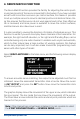
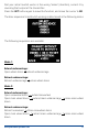
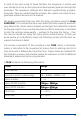
Select SERVO-MATCHING in the Main menu, and the following screen display
appears:
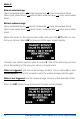
To ensure accurate servo matching, the output to be adjusted must rst be
initialised. Leave the associated transmitter stick at centre. Move the cursor
to INIT OUTPUT and press the SET button. Now move the transmitter stick
to both end-points.
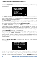
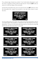
The graphic display shows the movement of the upper arrow, which indicates
the input signal. The bar inside the box shows the movement of the output.
The three lower arrows indicate the centre and end-point positions which are
‘learned’ in this process.
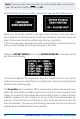
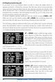
Note: if the channel has not yet been initialised, it is not possible to select
the START SERVOMATCHING and REVERSE SERVO points.