
Instruction Manual

8 PowerBox-Systems − World Leaders in RC Power Supply Systems
the CORE. As with the ailerons, you again assign a transmitter control to the aps. If each ap is operated by a
separate servo, you won’t notice anything unusual: you simply assign the aps to your preferred servo outputs.
However, if you also want the ailerons to double as aps, or want the ailerons to be mixed in to the aps, you
also assign the aileron outputs to the ap function. These functions are now superimposed, i.e. the mixing is
accomplished simply by assigning the servos.
At a later stage you can adjust the servos individually, both for the Aileron function and the Flap function. Servo
travel, centre and direction can be set separately for both functions!
An even clearer example of this exceptional feature relates to models with a delta wing. If you select a delta using
the Assistant, the correct functions are assigned automatically. To clarify this, the manual method would be as
follows:
As an example servos 1 and 5 are assigned to Aileron. Servos 1 and 5 are also assigned to Elevator. Since the
servos are installed in a mirror-image arrangement, it is logical that the servos always operate as ailerons, re-
gardless of whether the pilot moves the elevator stick or the aileron stick. Now we switch to the Elevator function
and reverse the direction of rotation of one servo. The elevator function now works correctly, but the “reversed”
elevator function has no effect on the servo direction when an aileron command is applied, i.e. the ailerons still
work correctly. That’s all there is to setting up a “delta mixer”.
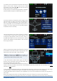
Back to our Wing screen: when all the assignments are complete, press the
-button amongst the quick-select
buttons at the bottom in order to return to the overview.
You can now continue assigning transmitter controls and servos to all the remaining functions. When everything
is nished, touch Continue at bottom right. The functions and servo assignments are complete.
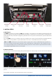
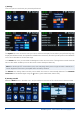
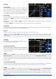
3. FUNCTION MENU
You now arrive at the most important screen display:
the Function Overview. In principle, the set-up of the
whole model is carried out from this starting point. The
display is arranged logically from left to right:
Function Transmitter control Trim Setup
Failsafe Servo(s)
The individual points in detail:
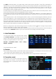
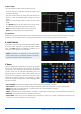
A. Function
Each function always contains a transmitter control, the associated trim, the settings for the transmitter control
- such as Expo and Travel, Failsafe or Hold - and the assigned servos.
Each function can also be renamed just as you wish at this screen: simply touch the Function name.
B. Transmitter control
At this point you can assign a transmitter control or a
xed value to the function. A transmitter control may
be a primary stick, a proportional control, a switch or a
push-button.