
Instruction Manual


14 PowerBox-Systems − World Leaders in RC Power Supply Systems
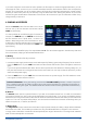
The Rescan sensors button is required if you wish to connect new sensors while the system is operating.
Touching the button forces the system to re-collect all sensor information on the P²BUS. In principle, all sensor
information is collected automatically every time the system is switched on.
Technical information: the PowerBox CORE telemetry system and the P²BUS are designed in such a way
that each sensor supplies its own information, including sensor name, unit, number of sensor values, decimal
point, priority and other data. A new sensor designed for use with the P²BUS can be connected to the system
at any time without updating the transmitter.
The advantage of the system is that all the text information relating to the sensor values is collected only
when the system is switched on, i.e. when the system is booting.
Once the system is running, only the pure sensor values are transferred; this permits very fast data transmis-
sion with maximum exibility, and ensures a thoroughly user-friendly system.
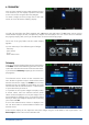
Behind the individual sensor values you will nd the Alarm button. The Alarm menu allows you to set four alarm
thresholds: one yellow alarm and one red alarm for each direction. This enables you to select different thresholds
coupled to different sounds, text, or vibration modes.
For example, you might set up battery capacity alarms for an electric model: a yellow audible alarm when there
is just sufcient energy remaining for one minute of ight; a red audible alarm with vibration for twenty seconds.
Touching the Back button returns you to the Sensor overview. Press OK at the bottom when you have completed
all the settings.
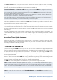
The widget now appears in the location where you started, but widgets can also be placed in any position. This
is accomplished by holding your nger on the screen until the widgets start to icker; you can now move the
widgets around on the screen. To x the widgets in position again, simply wait a few seconds or press the Home
button.
Servo values, Timers, Quick-select menu
Widgets can also be set up for individual servo outputs, timers or menu entries, in exactly the same way as de-
scribed for telemetry values. The procedure is identical: hold your nger on a vacant space in the main screen,
then make your selection as already described.
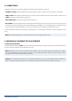
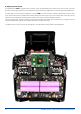
7. CHARGING THE TRANSMITTER
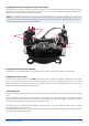
If you wish to charge the CORE, the rst step is to open the front cover. Locate the two plugs attached to the
mains PSU, and insert either one into the charge socket. If the battery symbol is displayed large and ashing on
the screen, this means that you have a reserve for about 20 - 30 minutes. You must charge your CORE at this
point, if not sooner. For safety reasons the CORE does not feature a battery cut-off. Never allow the transmitter
to become deep-discharged!
The LEDs light up red when the batteries are on charge, and green when the charge process is complete. The
charger can be left connected to the CORE after charging without causing damage, as the internal charge control
circuits regulate the charge process completely automatically.
The battery charge process takes about 3.5 hours from the fully discharged state.
The CORE can also be recharged while it is switched on, e.g. for protracted programming work.
Note: in addition to the bar display at top left on the screen, you can also set up the transmitter to display
its own exact battery voltage on the main screen in the form of a telemetry widget, and set a corresponding
alarm. The transmitter is tted with two internal 7.2V Li-Ion batteries of 3400 mAh capacity. Sensible alarm
values would be 6.8V for an orange alarm, and 6.6V for a red alarm.
Note: the mains PSU is the same type used for PowerBox Batteries and PowerPaks, and can also be used
to recharge these batteries.