Instruction Manual
Dear PowerBox pilot, Many thanks for placing your trust in us, and purchasing our PowerBox CORE. You have chosen an extremely unusual radio control system: the CORE has great presence and allure, which you cannot fail to appreciate when you pick up the transmitter for the first time. The CORE fits perfectly in your hands, and is the perfect tool for controlling your valuable models with precision.
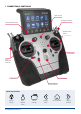
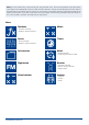
1. CONNECTIONS, CONTROLLS Light sensor 8 Toggle switches Quick-select buttons Optional stick switch Loudspeaker 4 proportional controls 4 digital trims On / Off switch 4 push-buttons Quick-select buttons Screen unlock www.powerbox-systems.
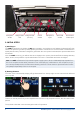
Headphone socket Charge status Charge socket LED (10-16V) USB-A socket Microphone input Micro USB socket Servo tester/ PPM output 2. INITIAL STEPS a) Switching on The CORE is switched on by holding the -button pressed in until it lights up red. Release the button briefly, then confirm the power-on process by briefly pressing the button a second time. The transmitter is switched off in exactly the same way.
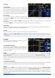
Note: you can transfer any menu point to your own personal menu. This is accomplished simply by holding your finger on the appropriate menu for a few seconds. When the “Person symbol” appears, the menu point is transferred into your personal menu, which you can access conveniently using the quick-select button at the bottom of the screen. If you wish to remove a menu point again, use the same procedure: keep your finger on the menu symbol in question, and that entry is duly erased.
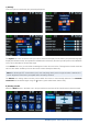
c) Settings This menu point is used to set your personal preferences. The System sub-menu is used to enter your name, set the time display format, select your preferred language, display the software version and update the software when necessary. Another important point is the Calibration menu; this is described in full at a later stage. In the Screen sub-menu you can select the background colour and icon colour.
To create a new model, briefly touch the + button at the bottom of the screen. Assign a name to your model, and confirm your choice with OK. You will now see the Select screen for the model type. At this point you can select the appropriate model type, with the additional options of delta wing and V-tail. On the next screen you select one of the ranges on the right-hand side, e.g. Wing. The screen now shows a diagram of a wing corresponding to your chosen type.
the CORE. As with the ailerons, you again assign a transmitter control to the flaps. If each flap is operated by a separate servo, you won’t notice anything unusual: you simply assign the flaps to your preferred servo outputs. However, if you also want the ailerons to double as flaps, or want the ailerons to be mixed in to the flaps, you also assign the aileron outputs to the flap function. These functions are now superimposed, i.e. the mixing is accomplished simply by assigning the servos.
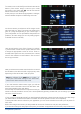
C. Trim a) Trim control It is necessary to assign a trim control as the first step here. This can be one of the four trims located adjacent to the primary sticks, or two of the four rubberised push-buttons. If you select the push-buttons, the buttons always work together left and right as the trim. b) Trim mode You can choose any of four different trim modes. The standard one is Centre mode: in this mode any change to the trim only affects the central range, i.e. not the end-points.
e) Curve editor The curve editor is used to set up special curves. - The first step is to select the number of points: up to 33 can be specified. - Use the arrow buttons to select the point which you wish to move; the selected point changes colour to green. - Adjust the percentage value to shift the point up or down. - The Smooth option can be used to even out the curve, and thereby avoid jerks in the servo’s response. - Raw removes the effect of the curve smoothing.
If you wish to adjust a servo’s travel or centre position, the first step is to touch the appropriate button; you can now adjust the value. As soon as you move the associated stick, the Select button shifts to the corresponding position.
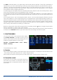
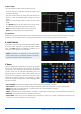
5. MIXER The free servo mixers represent an additional method of mixing functions with each other. Servo mixing by servo assignment has already been described in the Function menu, but this option also enables you to mix functions with each other with a response curve. You can create a new mixer by selecting the Mixer menu and pressing +. You can also immediately rename the Mixer to your own choice by touching the Mixer button. Press the Setup button on the right in order to program the mixer.
6. TELEMETRY Once you have created a new model and bound one or more receivers, you can display important information on the main screen using the telemetry widgets. To create a widget, touch an empty area of the main screen, and you will see the following display: You will now see twelve grey fields, together with a P+ button and a P- button. The P+ button can be used to create additional pages, so that more telemetry widgets can be displayed.
The Rescan sensors button is required if you wish to connect new sensors while the system is operating. Touching the button forces the system to re-collect all sensor information on the P²BUS. In principle, all sensor information is collected automatically every time the system is switched on.
8. CONNECTIONS Under the front cover you will find additional sockets (see illustration on page 4): - Headphone socket: stereo headphones can be plugged in here for spoken vario or telemetry messages. - USB-A socket: this accepts a USB stick, which can be used to update the radio control system. Data from the CORE can also be copied onto the USB stick. - Micro USB socket: for direct exchange of data with a PC.
b) Opening the transmitter As standard the CORE is supplied in the correct mode, as specified by the customer, but some users may find that the centring spring tension or the ratchet function needs to be adjusted to meet their personal preferences. The first step is to remove the handrests. Lay the CORE on a soft surface – ideally a thick layer of foam. Now undo and remove all ten socket-head screws holding the back cover.
c) Adjusting the tension of the primary stick centring springs The centring spring tension can be adjusted using screws 1 and 2 after loosening the corresponding locknuts. Tightening the screw further increases the spring tension. If you find it impossible to set your preferred spring tension, we can supply a range of stronger springs. Note: if you tighten the screw too far, you may find that the lower spring tensioner partially moves out of its guide.
10. CALIBRATING THE TRANSMITTER CONTROLS Naturally the PowerBox CORE is supplied with all functions correctly calibrated. However, if you wish to swap a switch or replace a broken switch, we recommend that you re-calibrate the new switch. Re-calibration is also necessary if, for example, you limit the throttle stick travel, or change the transmitter mode mechanically. Move to the Calibration menu by this route: Settings System Calibration.
13. SERVICE NOTE We are anxious to offer good service to our customers, and to this end we have set up a Support Forum which deals with all queries concerning our products. This relieves us of a great deal of work, as it eliminates the need to answer frequently asked questions time and again. At the same time it gives you the opportunity to obtain help quickly - all round the clock and even at weekends. All the answers are provided by the PowerBox team, which guarantees that the information is correct.
07/2019 FCC This device complies with part 15 of the FCC Rules. Operation is subject to the following two conditions: (1) This device may not cause harmful interference, and (2) this device must accept any interference received, including interference that may cause undesired operation.