
User manual PowerSwitch PowerBox - MPX-JR sockets

GUARANTEE CONDITIONS
We are able to grant a 24 month guarantee on our PowerSwitch from the initial date of
purchase. The guarantee covers proven material faults, which will be corrected by us at
no charge to you.
The guarantee does not cover damage caused by incorrect usage, e.g. reverse polarity,
excessive vibration, excessive voltage, damp, fuel, and short-circuits. The same applies to
defects due to severe wear.
LIABILITY EXCLUSION
We are not in a position to ensure that you observe our instructions regarding installation
of the PowerSwitch, fulll the recommended conditions when using the unit, or maintain
the entire radio control system competently.
For this reason we deny liability for loss, damage or costs which arise due to the use or
operation of the PowerSwitch, or which are connected with such use in any way. Regard-
less of the legal arguments employed, our obligation to pay damages is limited to the in-
voice total of our products which were involved
in the event, insofar as this is deemed legally
permissible.
We wish you loads of fun with your new Power-
Switch!
Donauwoerth, December 2020
PowerBox-Systems GmbH
Ludwig-Auer-Straße 5
D-86609 Donauwoerth
Germany
+49-906-99 99 9-200
+49-906-99 99 9-209
www.powerbox-systems.com
SERVICE NOTE
We make every effort to provide a good service to our customers, and have established a
Support Forum which covers all queries relating to our products. It gives you the oppor-
tunity to obtain help quickly all round the clock - even at weekends. All the answers are
provided by the PowerBox Team, guaranteeing that the information is correct.
Please use the Support Forum before you contact us by telephone.
You can nd the forum at the following address:
www.forum.powerbox-systems.com
Instruction Manual
12/2020
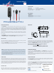
DIMENSIONS
SPECIFICATION
Voltage range: 4.0 - 12.6V
Power supply: LiPo/LiIon, LiFe, NiCd/NiMH
Max. continuous current: up to 20 Ampere when switched on
Temperature range: -10°C to +60°C
SET CONTENTS
- PowerSwitch
- Mounting screws
- Operating instructions in German and English
- Cutting template
PRODUCT DESCRIPTION
The PowerSwitch is an extremely durable, reliable mechanical switch. The switch itself
is housed in a sealed, dustproof metal case. Four oating silver-plated double contacts
switch the positive conductor alone. The negative conductor is looped through without
contacts of any kind; this alone reduces the theoretical likelihood of failure by 50%! Two
ball latches keep the switch in the selected switched position even when subjected to
severe vibration.
The green LED shows the switched state; it is not a battery voltage indicator. The switch
positions are marked on the case. The switch is ON when the slider is moved towards the
LED - position I.
The PowerSwitch has also proved an excellent choice for ignition systems, and especially
for twin ignition systems and four-cylinder engines with two ignition systems.
INSTALLATION
The internal packaging is designed to be used as a template for marking the switch
opening. Cut or saw out the opening outside the marked line.
Although the PowerSwitch is extremely resistant to vibration, it should always be installed
in a position in the fuselage where vibration levels are low.
Note: The fuselage sides of large GRP power models are actually not suitable for
mounting switches - regardless of type - because they are always subject to severe
vibration and oscillation. You can remedy the situation by cutting a small plywood plate
(2.5 to 3 mm thick) 2 to 3 cm larger than the switch opening, and gluing it on the inside
of the fuselage at the appropriate point.
When glued in place, the plate acts as a vibration damper, and also provides plenty of
material for the switch retaining screws.
CONNECTIONS
The two connecting leads (blue / red) which are connected to the receiver or some other
consumer unit consist of 0.34mm² cable. Always connect both plugs to the receiver: one
to the receiver’s battery socket, and the second to any other vacant channel output. This
ensures that at least one connector contact carries current to the receiver and servos at
all times. At the same time, the current required for your system is carried by both leads
(twice the conductor cross-section) and both contacts, and this reduces voltage uctua-
tions and improves servo performance.
BATTERY TYPES
We always recommend the use of top-quality, low-impedance rechargeable batteries to
power your receiving system. Any type of rechargeable battery (LiPo / LiIon, LiFe, NiCd
/ NiMH) up to 12.6V can be used. The PowerSwitch does not feature voltage regulation.
PowErSwitch