
User manual PowerBox Mercury SRS with OLDED Screen and GPS

18
PowerBox-Systems − World Leaders in RC Power Supply Systems
- You can now release the aileron stick: the PowerBox maintains this position. You now
have both hands free, and can adjust the position accurately with one hand, using
buttons I and II, whilst checking the length (matching) of the disconnected ball-link at
the horn with the other hand.
- Press the SET button again to conclude this adjustment.
- Complete the set-up procedure for the centre position and both end-points before
re-connecting the servo linkage.
- If you need to carry out further adjustments to another end-point or centre position,
move the aileron stick in the desired direction again, and press the SET button again
to start the procedure.
- Repeat the procedure with all the servos connected to the same control surface.
Note: if your model is tted with very large ailerons, it can be advantageous not to
match the servos with 100% accuracy. If the servos are precisely matched, gear-
box play may allow aileron utter to develop. You can eliminate this risk as follows:
rst match the servos exactly to each other, and then press buttons I or II two or
three times to reduce the effect of lost motion in the servo gears to a controlled
extent.
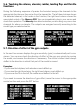
b) Reversing one output where servos are installed in a mirror-image arrangement;
in this example right and left landing aps, connected to OUT E and OUT K
- Disconnect the linkage to the left-hand landing ap, to avoid the servo being subjec-
ted to severe forces during the adjustment procedure.
- The right-hand landing ap servo is connected to OUTPUT E; carry out the mecha-
nical adjustment, then ne-tune it using the transmitter until the centre position and
maximum end-points are correct.
- Now select the channel to be matched in the servo-matching menu. In this example
it is OUTPUT K.
- Move the landing ap switch to the center position - not one end-point!
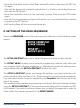
- Now select: INIT OUTPUT
- The output is initialized by moving the switch on your transmitter to both end-points.
If you have set up a delay at the transmitter, wait until the end-point has been reached.
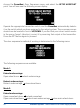
- Use the SET button to select REVERSE SERVO. A tick appears after the function, and
the left-hand landing ap servo now operates in the correct direction.
- Move the cursor to START and press the SET button.
- Use button I or II to adjust the center position of the left-hand landing ap to the exact
position required, then press the SET button.