
User manual PowerBox Mercury SRS with OLDED Screen and GPS

www.powerbox-systems.com 15
This completes the Setup Assistant procedure. In the following stage all the remaining
functions, such as retract system, brakes and lighting, are assigned and adjusted whe-
re necessary using the servo-matching function.
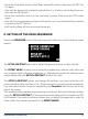
6. OUTPUT MAPPING
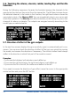
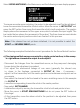
Since the Setup Assistant does not cover all the
functions, Output Mapping is employed to assign
additional functions to the outputs; it is also pos-
sible to shift existing functions to other outputs.
As can be seen in the screen-shot above, the left-hand column shows the output letter;
the centre lists the assigned function or the transmitter channel; and the right-hand
column is used to set each output to Hold or Failsafe if the radio link should fail.
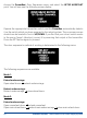
The following set-up facilities are provided for FUNCTION:
- DIRECT 1 to 18:
Depending on your radio control system, channels 1 to 18 can be output directly, as
they arrive from the transmitter.
Example: at your transmitter the wheel brakes are assigned to channel 9, and you
wish to connect the brakes to output E. Move the cursor to E and conrm your choice
by pressing the SET button. Set the following at E: DIRECT 9. The servo connected to
output E now follows commands from channel 9 at your transmitter 1:1 - unless, that
is, you have made adjustments using the servo-matching facility.
- GY AILERON, ELEVATOR, RUDDER:
If you select one of these functions, the output is linked internally with the iGyro out-
put. Two outputs are available for each axis: GY AILE-R, GY AILE-L, GY ELEV-R, GY
ELEV-L, GY RUDD-A, GY RUDD-B.
Each of these axes is individually variable for gain, direction of effect and gyro function.
Example:
a) The right-hand aileron is connected to GY AILE-R, the left-hand aileron to GY AILE-L.
b) The rudder is connected to GY RUDD-A, the steerable nosewheel to GY RUDD-B.